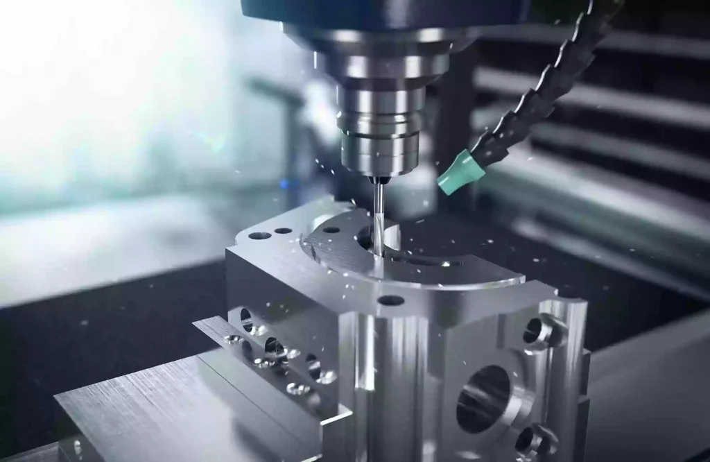
Five-Axis Sidewall Finishing of Aerospace Structural Parts: Tool Axis Control Challenges and Optimization Methods in NX Programming
Aerospace structural parts typically feature complex spatial contours, deep pockets, thin walls, and multi-angled sidewalls. As part designs grow more intricate, traditional three-axis machining is increasingly limited in tool accessibility, number of setups, and machining efficiency. Five-axis simultaneous machining adapts to machining requirements from different directions through coordinated multi-axis motion between the tool and the workpiece, giving it clear advantages in machining complex sidewalls, pockets, and spatial surfaces on aerospace structural parts.
However, selecting a five-axis operation does not automatically produce an ideal toolpath. This is especially true in sidewall finishing, where the tool must continuously adjust its orientation to follow the wall geometry. If the tool axis direction is poorly controlled, problems may arise, such as abnormal approach and retract directions, rapid tool axis reversals, and discontinuous machining in local areas, ultimately affecting surface quality and machining stability.
Drawing on a case study of machining aerospace structural parts on a German GROB five-axis machine tool, this paper focuses on the contour milling operation in NX (UG) and analyzes two typical programming challenges in five-axis sidewall finishing. It then presents solutions that adjust the engage vector and use auxiliary geometry to control tool axis transitions.
GROB Five-Axis Machine: The Hardware Foundation for Machining Complex Aerospace Structural Parts
Before analyzing the CAM programming, it is worth understanding the structure of the machine tool used in this case.
This case uses a German GROB five-axis machine. Compared with conventional five-axis machines, its worktable motion structure and spindle layout have distinctive design features that provide greater motion space for multi-angle machining of large, complex parts.
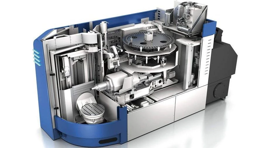
Large A-axis tilt angle improves machining capability for complex orientations
The A-axis worktable of this machine can tilt up to 230°, supporting a wide range of workpiece orientations.
Aerospace structural parts often have machining surfaces facing multiple directions, and some sidewalls can only be completed if the tool approaches from a special angle. A wide tilt range gives more options for positioning different machining surfaces and for tool access.
In addition, the machine supports inverted (upside-down) machining. During cutting, chips can leave the machining area more smoothly under gravity, which reduces the effect of chip accumulation on the tool and workpiece surface and improves chip evacuation in deep pockets and complex structural areas.
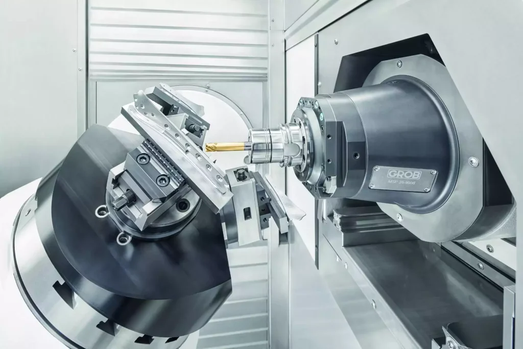
Tunnel-type spindle design solves the space problem for large workpieces and long tools
Another notable feature is the tunnel-type spindle structure used on GROB machines.
When machining large aerospace structural parts, the workpiece is often large and some areas are deep, requiring long tools. If the machine’s internal motion space is insufficient, then even if the tool itself can reach the target position, machining may still be impossible because of interference among the spindle, tool, and workpiece.
The tunnel-type spindle design allows the spindle to retract toward the rear of the machine, providing extra motion space for combinations of large workpieces and long tools. Within the available travel and motion range, this allows more flexible planning of machining orientations and reduces spatial limitations at some complex machining positions.
It should be noted that the machine structure only provides the foundation of motion capability. Whether a part can actually be machined also depends on rotary axis travel, tool length, tool holder dimensions, workpiece clamping, and the machine’s collision limits.
For five-axis machining, the machine structure determines the upper limit of the available motion space, while CAM programming determines how to make reasonable use of that motion capability.
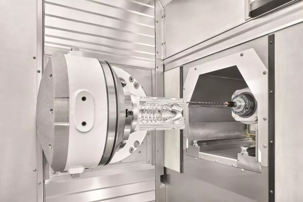
NX Five-Axis Sidewall Finishing: Why Choose Contour Profile?
In NX programming, the Contour Profile operation can be used for five-axis sidewall finishing.
The main characteristic of this operation is that it machines the wall with the side of the tool rather than relying solely on the tool’s end face. For sidewalls with ruled-surface features, this approach makes full use of the tool’s flank, allowing a large area of the wall to be finished in a single continuous pass. It is well suited to semi-finishing and finishing of sidewalls.
However, even though all of these are sidewall machining tasks, different geometries can place completely different demands on tool axis control.
For example, when machining a conventional S-shaped sidewall, the wall has varying curvature, but the tool axis generally stays relatively stable as the tool moves along the path, and the change is easy to control.
Complex spatial sidewalls are a different matter.
Because the position and angle of the sidewall change continuously in space, the tool must not only move along the machining contour but also adjust its orientation in step with the wall’s geometry. In some areas, the spindle may even need to rotate through a large angle.
If the toolpath is generated with default parameters, the approach and retract directions of the tool may be unreasonable, or the tool axis may suddenly reverse direction in some local areas.
Therefore, the key to five-axis sidewall finishing is not merely generating a complete machining path, but also ensuring that the tool maintains a reasonable spatial orientation throughout the entire machining process.
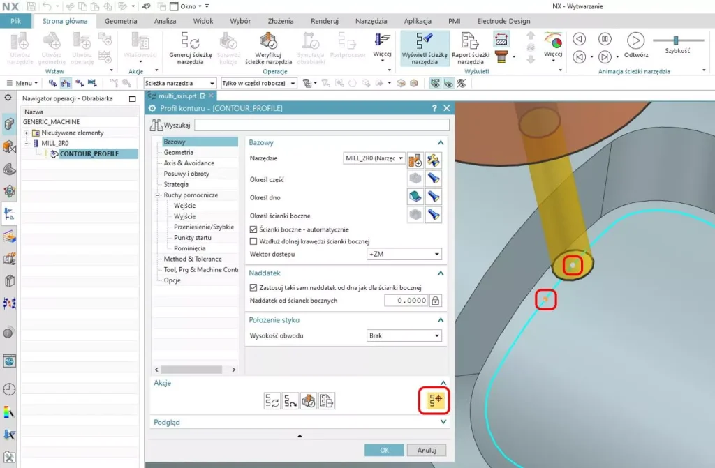
Problem 1: Incorrect Approach and Retract Directions — How to Set the Engage Vector Correctly
After creating a Contour Profile operation in NX, if you simply select the floor and the sidewalls to be machined and then generate the toolpath, you may find that the tool’s entry and exit directions are unreasonable at certain positions.
This is especially true when the sidewall undergoes large changes in spatial angle. The generated toolpath may cover the target machining area, but the tool orientation during approach and retract may not match what was intended.
Cause of the Problem
An important difference between five-axis and three-axis machining is that the tool direction is not always fixed.
During machining, the tool axis must be adjusted according to the spatial position of the part surface. When the sidewall geometry changes sharply in angle, the spindle and rotary axes must change orientation accordingly.
If the approach and retract strategy does not fully account for this change, the tool may approach the workpiece from an unreasonable direction, or make unnecessary orientation adjustments when retracting.
Such problems not only increase the possibility of interference between the tool and the workpiece, but may also make the approach and retract motions less smooth, affecting machining stability.
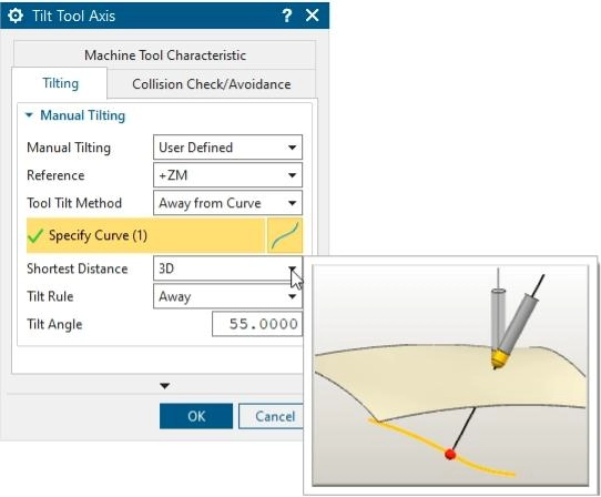
Key Parameter: Engage Vector (Approach Vector)
To solve this problem, focus on the engage vector parameter in the Contour Profile operation.
The engage vector defines how the tool is positioned relative to the machined wall and provides the directional reference the tool uses as it approaches the machining area.
In conventional sidewall machining, a fixed direction may be enough to produce acceptable approach and retract paths. However, when the geometric angle of the sidewall changes greatly, particularly when it involves a spatial turn of more than 180°, a fixed direction may not accommodate the actual spindle rotation required.
Parameter Adjustment: Changing from Fixed Direction to Away From Line
For the geometry in this case, the engage vector can be changed from “Fixed Direction” to “Away From Line.”
The main difference between the two settings lies in how the tool direction reference is defined.
“Fixed Direction” determines the tool orientation according to a specified fixed direction. When the sidewall turns sharply in space, it may fail to produce ideal entry and exit directions.
“Away From Line” determines the tool placement direction based on a corresponding geometric reference relationship. In this case, this approach better accommodates the large angular changes of the sidewall and makes the tool’s approach and retract directions more reasonable.
After modifying the parameter, recalculate the toolpath and focus on checking the following:
- Whether the tool enters from a reasonable direction when approaching the machining area.
- Whether there is any unnecessary spindle rotation when the tool retracts.
- Whether the tool, tool holder, and workpiece interfere with each other during approach and retract.
- Whether the rotary axis motion stays within the machine’s permitted range.
Adjusting the engage vector resolves the approach and retract orientation problem in complex sidewall machining first, laying the groundwork for the subsequent optimization of tool axis continuity.
Note that “Away From Line” is not a universal rule for all sidewalls exceeding 180°. The final choice should still be based on the specific geometry and toolpath simulation results.
Terminology note: NX’s English interface may label these options slightly differently depending on version (e.g., “Fixed Direction” and “Away from Line” under the Tool Axis / Drive settings). Please verify against your NX version’s actual menu wording before publishing.
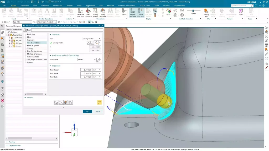
Problem 2: Rapid Tool Axis Reversal — How to Improve Machining Transitions
After resolving the approach and retract direction problem, you may encounter another, more difficult situation: the tool axis reverses rapidly in a local machining area.
In the generated toolpath, you can see that at certain positions the tool axis direction changes abruptly and sharply as the tool moves along the sidewall, with no smooth orientation transition between the two adjacent machining areas.
This phenomenon is fairly common on complex spatial sidewalls.
Why Does Automatic Tool Axis Control Cause Reversal Problems?
The Contour Profile operation provides an automatic tool axis control mode.
In this mode, NX calculates the tool axis direction from the normal of the trace curve at the bottom of the sidewall. For walls with relatively regular geometry, this calculation usually gives acceptable machining results.
However, automatic calculation does not mean the tool axis direction will be optimal under every complex geometric condition.
When the spatial angle, curvature, or local geometric relationships of the sidewall change greatly, the automatically calculated tool axis direction may change quite rapidly.
This is especially true at the junction between two machining areas. If there is no clear tool axis transition reference, rapid tool axis reversal may occur.
If the tool axis changes too quickly, it increases the motion burden on the machine’s rotary axes and may cause the cutting orientation to change suddenly. For high-requirement finishing of aerospace structural parts, such discontinuous orientation changes may also affect local surface quality.
Therefore, for complex spatial sidewalls, you cannot rely entirely on automatic tool axis calculation.
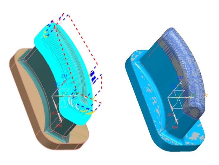
Optimization Approach: Establish a Tool Axis Transition Reference Through Auxiliary Geometry
If you only repeatedly adjust the conventional parameters of the Contour Profile operation, it is difficult to fundamentally change the geometric relationships on which the automatic tool axis calculation is based.
A more direct solution is to return to the NX modeling environment and create auxiliary geometry that establishes a clear reference direction for the tool axis change.
Specifically, an auxiliary line and the Divide Face command are used to split the originally continuous, complex sidewall into machining areas with clearly defined boundaries. Then, through the “Align to Edge” function in the tool axis strategy, the tool is made to control its orientation according to the specified boundaries.
The focus of this method is not to change the final geometry of the part, but to give the CAM tool axis calculation clearer reference conditions.
Specific Procedure
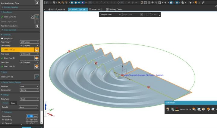
Step 1: Create an auxiliary line
First, return to the NX modeling environment and create a line based on the transition required between the two tool axis directions.
This line is not an ordinary marker; it is an important geometric reference for controlling the tool axis orientation later.
When creating it, determine the line’s direction according to the actual spatial position of the sidewall, so that it expresses the intended tool axis transition direction.
Whether the direction of the auxiliary line is reasonable directly affects the subsequent tool axis control, so it must not be created arbitrarily.
Step 2: Use the Divide Face command to split the surface
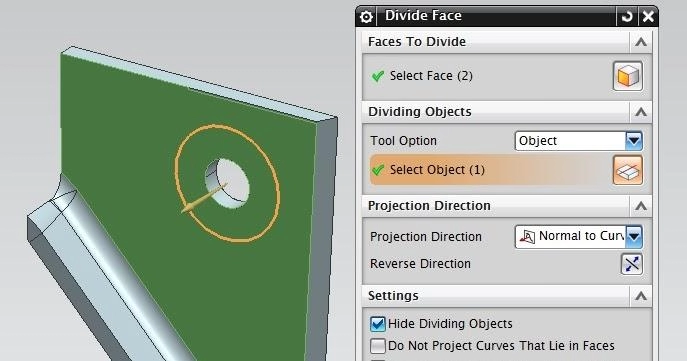
After creating the auxiliary line, use the Divide Face command to process the original sidewall and split the target surface into the corresponding machining areas.
The purpose of the split is to establish clear geometric boundaries so that the subsequent tool axis control can recognize and use the specified straight edge.
Note that Divide Face is mainly used for programming assistance and geometric reference, and should not change the final design contour required of the part. In practice, check whether the boundaries of the divided surfaces are continuous and whether the split affects the selection of the original machining areas.
Step 3: Change the tool axis strategy to Align to Edge
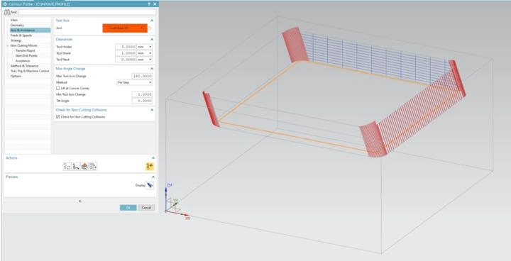
After the auxiliary geometry is prepared, re-enter the Contour Profile operation and, in the tool axis control options, change the original automatic tool axis mode to “Align to Edge.”
This option uses the straight edges between the top and bottom of the wall as the alignment reference for the tool, so that the tool can determine its orientation from the specified boundary.
For surfaces with clearly defined straight edges, this approach controls the tool axis direction more directly and reduces the undesirable changes that automatic calculation may produce under complex geometric conditions.
In this case, by turning the auxiliary line into a boundary reference usable by the tool axis strategy, the tool axis can be guided to make the transition between the two machining areas in the intended direction.
Step 4: Regenerate the toolpath and verify the results
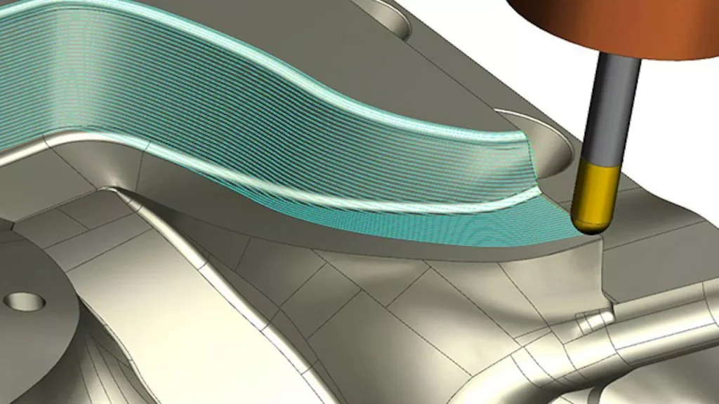
After adjusting the tool axis strategy, regenerate the Contour Profile toolpath.
Focus on the positions where rapid reversal previously occurred, and check whether the tool axis now changes in the intended direction and whether the transition between the two areas is smoother.
At the same time, use machine simulation to check the spatial relationships among the tool, tool holder, spindle, and workpiece, and confirm that the rotary axis motion does not exceed the machine’s limits.
Only after the toolpath, the tool axis variation, and the machine motion all meet requirements can the optimized toolpath be used for actual machining.
The Core of Five-Axis Sidewall Finishing: Let the Tool Axis Follow the Geometry, Rather Than Be Constrained by It
This case shows that the difficulty of five-axis sidewall finishing lies not entirely in the toolpath itself, but in how to keep the tool orientation reasonably matched to complex spatial geometry.
Contour Profile milling can machine sidewalls with the flank of the tool, reducing repeated passes and achieving high machining efficiency under suitable geometric conditions. However, when the sidewall changes from a conventional shape to a complex spatial surface, the approach and retract directions and the continuity of the tool axis become important factors affecting machining results.
This case used two different approaches:
First, adjust the engage vector. To address abnormal approach and retract directions on sidewalls with large spatial angles, the engage vector was changed from “Fixed Direction” to “Away From Line,” improving the tool orientation as it enters and exits the machining area.
Second, use auxiliary geometry to control tool axis transitions. To address the rapid reversal of the automatic tool axis on complex surfaces, an auxiliary line was created, the surface was divided, and the “Align to Edge” strategy was used to provide a clear geometric reference for tool axis changes.
The two methods address the approach and retract directions and the tool axis transitions during machining, respectively. They also illustrate an important programming principle in complex five-axis machining: do not rely entirely on the software’s automatic calculation, but instead actively establish reasonable tool axis control conditions based on the geometric features of the part.
The advantage of five-axis simultaneous machining lies not only in allowing the tool to approach the workpiece from more directions, but, more importantly, in using sound toolpath planning and tool axis control so that complex spatial sidewalls can be finished in a more continuous and stable manner.
Need a Manufacturing Partner for Complex CNC Machined Parts?
Complex components require more than advanced machining equipment. They also demand careful drawing review, practical DFM analysis, appropriate machining strategies, and reliable quality inspection throughout production.
At Xtmade, we provide custom 5 axis CNC precision machining services for complex metal and plastic components. From multi-axis machining and intricate structural features to tight-tolerance parts, our engineering and manufacturing teams work with your existing drawings, CAD files, and technical specifications to develop practical manufacturing solutions.
Whether you need aerospace structural components, precision housings, mechanical parts, or custom-machined assemblies, we can support your project from manufacturing evaluation to final inspection and delivery.
Have a part to manufacture? Send us your drawings or CAD files for a manufacturing review and quotation.