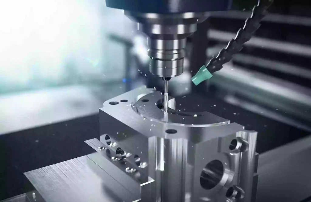
Tapping or Thread Milling Stainless Steel Valve Bodies? Start with Machine Capabilities
Threaded holes are common features in stainless steel valve bodies, but machining them reliably requires more than selecting the right tap or thread mill. The choice of threading process can directly affect machining time, tool life, dimensional accuracy, and the risk of scrapping an otherwise finished component.
Consider a stainless steel valve body with several M12 blind holes. Most of the machining operations have already been completed, and only a few threaded holes remain. Conventional tapping may finish each hole in seconds. However, if a tap breaks inside a blind hole, removing it can become a difficult operation. In some cases, the damage may extend beyond the threaded hole and compromise the entire part.
This is why threading decisions should not be based on cycle time alone.
Tapping is generally efficient for standardized threads and repeat production, while thread milling offers greater flexibility in thread size adjustment and can reduce the consequences of tool breakage. However, neither process is universally better. The right choice depends on the material, thread geometry, hole depth, machine capabilities, tooling, and production requirements.
At Xtmade, we approach threading as part of the overall CNC machining process. Understanding how the machine, cutting tool, and workpiece interact is essential to developing a reliable manufacturing solution.
Why Stainless Steel Threading Requires Careful Process Selection
Stainless steel can be challenging to machine because of its relatively low thermal conductivity, tendency to work-harden, and potential for material adhesion at the cutting edge. These characteristics become particularly important when machining internal threads, where the cutting area is confined and chip evacuation is limited.
During tapping, the tool engages multiple cutting edges simultaneously. As thread diameter and engagement depth increase, cutting torque can rise significantly. If the cutting conditions are not properly controlled, the tap may experience excessive loading, accelerated wear, or breakage.
Chip evacuation is another major concern. In blind holes, chips have limited space to escape. If they accumulate around the cutting edges or near the bottom of the hole, cutting resistance can increase and interfere with the tool’s movement.
Tool wear also affects thread quality. Material adhesion and built-up edge formation can change the effective cutting geometry, leading to inconsistent thread dimensions and poor surface finish.
For these reasons, stainless steel threading requires coordinated control of cutting speed, feed, lubrication, tool geometry, and chip removal. Choosing between tapping and thread milling is only one part of the process.
Rigid Tapping vs. Thread Milling: How the Processes Work
Although both processes produce internal threads, they rely on different machine movements and control capabilities.
Rigid Tapping: Synchronized Spindle and Z-Axis Movement
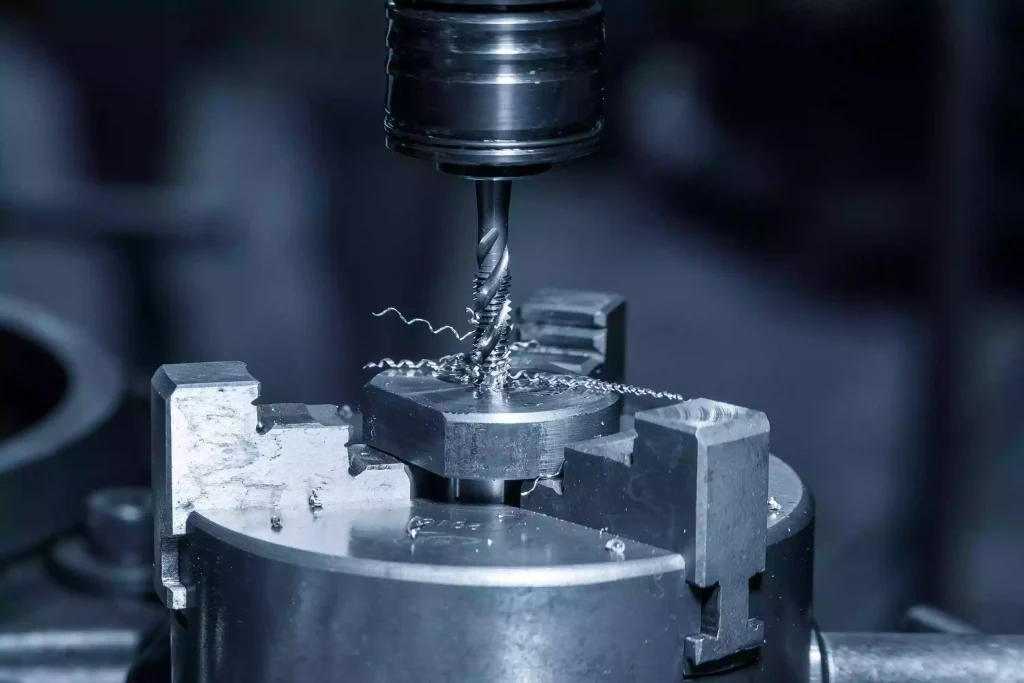
Rigid tapping is a widely used threading operation on CNC machining centers. During machining, the tap rotates while moving axially into the pre-drilled hole. The Z-axis feed must remain synchronized with spindle rotation according to the thread pitch.
For example, when machining an M12 × 1.75 thread, the Z-axis must advance exactly 1.75 mm for every complete spindle revolution. Once the programmed depth is reached, the spindle reverses direction, and the Z-axis must follow the same pitch relationship while the tap retracts.
This synchronization is essential. If spindle rotation and axial movement do not match, the tap experiences additional axial loading, which can increase tool wear and the risk of breakage.
A suitable rigid tapping setup therefore requires reliable spindle synchronization and sufficient torque throughout the operating speed range. The tool holder also matters. Synchronous tapping holders with limited axial compensation can help absorb minor synchronization errors, but they cannot compensate for inadequate machine control.
Thread Milling: Coordinated X, Y, and Z-Axis Movement
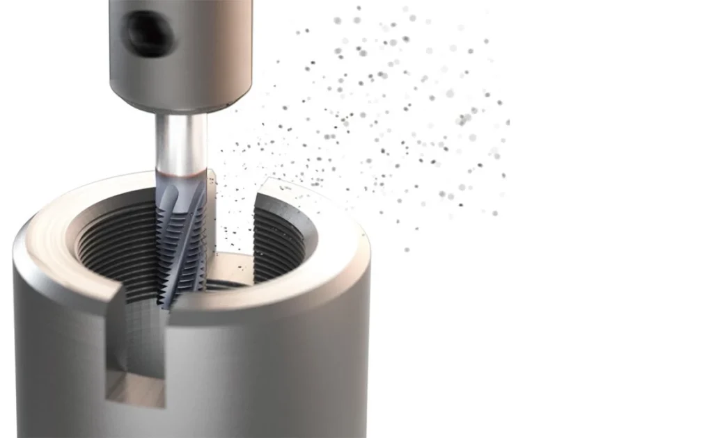
Thread milling uses a different approach. Instead of moving directly along the hole axis like a tap, a smaller milling cutter rotates while the machine guides its center along a helical path around the hole.
The cutter diameter is smaller than the internal thread diameter. As the tool moves around the hole, the X and Y axes generate the circular motion while the Z-axis advances according to the thread pitch.
For a 1.75 mm pitch, the tool center moves 1.75 mm in the Z direction during each complete revolution around the hole.
Unlike rigid tapping, thread milling depends on coordinated three-axis interpolation. The CNC control system must support helical interpolation, and the CAM software and postprocessor must generate the correct toolpath.
A standard three-axis vertical machining center can perform conventional internal thread milling when the thread axis is parallel to the spindle. Five-axis machining is not inherently necessary for this operation.
The main difference is therefore straightforward: rigid tapping depends on accurate spindle-to-axis synchronization, while thread milling depends on accurate coordinated axis movement.
Machine Tool Capabilities That Affect Threading Performance
A machine tool’s maximum spindle speed and rated power do not tell the whole story. Different threading operations place different demands on the spindle, control system, and feed axes.
Spindle Torque Matters More Than Maximum Speed
When tapping larger threads in stainless steel, machining often takes place at relatively low spindle speeds. Under these conditions, available spindle torque at the actual tapping speed is more important than the maximum RPM listed in the machine specifications.
For example, a machining center with a maximum spindle speed of 12,000 RPM does not necessarily provide sufficient torque at the lower speeds required for M12 tapping in stainless steel.
The actual torque curve should be checked against the intended cutting conditions. If the machine uses a geared spindle, the selected gear range must also be considered.
When evaluating a machine for a specific tapping application, we recommend checking:
- Spindle torque at the intended tapping speed, rather than relying only on rated power or maximum RPM.
- Available torque in the selected gear range, where applicable.
- Rigid tapping synchronization and spindle reversal performance.
- Tool holder compatibility and the cutting tool manufacturer’s recommended conditions.
The most reliable way to assess capacity is to provide the machine manufacturer with the material grade, thread specification, thread depth, and proposed tooling. This allows the spindle’s actual performance to be evaluated against the application.
Interpolation Accuracy for Thread Milling
Thread milling places different demands on machine performance. Since the cutter follows a helical path, the X, Y, and Z axes must move together while maintaining the programmed geometry.
Interpolation accuracy, servo response, and motion stability can all influence the final thread dimensions. This becomes particularly important when machining fine-pitch threads or threads with tight dimensional tolerances.
A machine may be able to execute a thread milling program without generating an alarm, but that does not automatically mean the finished thread will meet specification.
Actual cutting trials are necessary to evaluate tool loading, vibration, surface finish, and dimensional consistency under machining conditions.
Coolant Delivery and Chip Evacuation
Coolant delivery is another important consideration when machining deep or blind threads in stainless steel.
Through-spindle coolant can help deliver coolant closer to the cutting zone when used with compatible tooling. Depending on the hole geometry and cutting conditions, this may improve cooling and chip evacuation.
However, coolant pressure alone cannot solve every chip removal problem. Tool flute geometry, cutting parameters, hole depth, and chip formation must also be considered.
A stable threading process requires all these factors to work together.
When Should You Choose Tapping or Thread Milling?
The most suitable process depends on the part’s requirements rather than a general preference for one machining method.
When Tapping Is the Better Choice
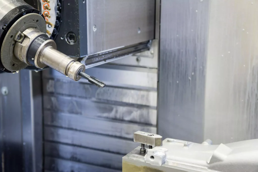
Tapping is often the preferred option for production runs involving many identical threaded holes, provided the machine has adequate synchronization, spindle torque, and chip evacuation capability.
Its main advantage is productivity. A tap can cut the full thread in a single axial operation, making it efficient for standardized thread sizes and repetitive production.
The process is also relatively straightforward to program, and standard taps are widely available in different materials, coatings, and geometries.
For stainless steel components, however, the tap must be selected according to the material grade, thread geometry, hole type, and chip evacuation requirements. Blind holes require particular attention because the tap needs sufficient clearance for its cutting chamfer and chip management.
If the required full thread depth is too close to the bottom of the drilled hole, the risk of chip accumulation and tool breakage increases. The drilling depth and tapping strategy should therefore be evaluated together.
When Thread Milling Makes More Sense
Thread milling becomes attractive when tool breakage carries a high financial risk, when thread dimensions need adjustment, or when the component has demanding machining requirements.
Because the cutter is smaller than the hole, a broken thread mill is generally easier to remove than a broken tap trapped inside a threaded hole. This can be particularly valuable for expensive components that have already undergone several machining operations.
Thread milling also offers flexibility in thread diameter. Within the cutter’s design limitations, different thread diameters can be produced by modifying the programmed toolpath rather than changing to a different tap for every diameter.
However, thread milling is not automatically more economical. It may require longer machining cycles, more sophisticated CAM programming, and additional toolpath verification.
For large production quantities with standardized threads, tapping may still offer a lower overall manufacturing cost.
Comparing the Two Processes
| Evaluation | Rigid Tapping | Thread Milling |
| Machine movement | Synchronized spindle and Z-axis | Coordinated X, Y, and Z axes |
| Typical cycle time | Generally shorter | Generally longer |
| Machine requirement | Rigid tapping capability | Helical interpolation |
| Spindle torque | Important, especially for larger threads | Must support the cutter’s cutting load |
| Thread size adjustment | Usually requires a different tap | Can be adjusted through the toolpath |
| Blind hole machining | Requires careful chip and bottom clearance management | Requires tool clearance and chip evacuation |
| Tool breakage | Broken taps can be difficult to remove | Broken cutters are generally easier to remove |
| Typical applications | Repetitive, standardized threading | High-value parts and applications requiring size flexibility |
Blind Holes, Deep Threads, and Other Machining Considerations
Even with the right machine and cutting tool, thread quality can be affected by details in the part design and machining sequence.
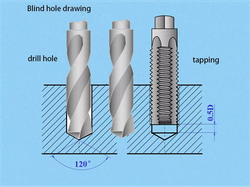
Allow Sufficient Clearance at the Bottom of Blind Holes
The specified full thread depth is not the same as the required drilling depth.
During tapping, additional space is needed for the tap’s cutting chamfer, chip evacuation, and safe tool withdrawal. If the available depth is insufficient, the tap may encounter excessive resistance before reaching the required thread depth.
Thread milling has different clearance requirements, but the tool still needs enough space for its cutting length, helical entry, and exit movements.
Before programming the operation, the following dimensions should be reviewed:
- Required full thread depth.
- Drill diameter and actual drilling depth.
- Bottom-hole geometry and available clearance.
- Effective cutting length of the selected tool.
- Entry and exit space for the programmed toolpath.
These considerations are particularly important for deep blind holes, where even a small programming or dimensional error can affect machining reliability.
Understand the Difference Between Tool Feed and Cutter Center Feed
One detail that is often overlooked in thread milling is the difference between the cutting edge’s feed rate and the cutter center’s programmed feed rate.
During internal thread milling, the cutter center follows a smaller circular path than the cutting edge along the thread profile. As a result, the two paths cover different distances over the same angular movement.
Tool manufacturers may specify cutting feed based on the cutting edge or thread profile, while CAM software may calculate the programmed feed based on the cutter center.
These values are not always interchangeable.
If the recommended cutting-edge feed is entered directly as the cutter center feed without the appropriate compensation, the actual cutting conditions may differ from the intended values.
Before running the program, confirm how the CAM system calculates feed rates and whether the postprocessor applies the correct compensation.
Coolant and Chip Removal Must Be Considered Together
Stainless steel can produce long, adhesive chips that are difficult to remove from confined cutting areas.
For tapping, tool geometry should be selected according to whether the hole is through or blind. Spiral-flute taps are commonly considered for blind-hole applications because they help direct chips upward, while other flute designs may be more suitable for through holes depending on the chip formation and material.
Thread milling also requires effective chip evacuation. If chips remain trapped between the cutter and the hole wall, they may be recut, increasing tool wear and affecting the thread surface.
The machining strategy should therefore account for tool geometry, coolant delivery, cutting parameters, and toolpath design rather than relying on spindle speed adjustments alone.
How to Verify Finished Thread Quality
Completing the threading operation does not necessarily mean the part meets the drawing requirements.
For stainless steel valve bodies and precision mechanical components, thread dimensions, thread form, surface condition, and functional fit all need to be considered.
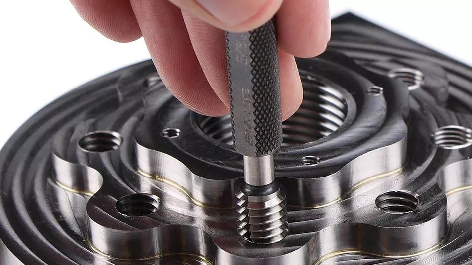
Thread Plug Gauge Inspection
Go and No-Go thread plug gauges are commonly used to verify internal thread acceptance.
The Go gauge checks whether the thread can achieve the required functional engagement, while the No-Go gauge checks whether the thread exceeds the applicable dimensional limits.
Inspection should follow the relevant thread standard and acceptance requirements. A gauge that can enter the hole does not, by itself, prove that every thread characteristic is correct.
Thread Pitch Diameter and Profile
For applications with tighter thread requirements, pitch diameter, pitch, and thread profile may also need to be evaluated.
Dimensional deviations can result in excessive assembly force, loose fits, or inconsistent connections, even when the thread appears acceptable visually.
Thread Depth, Chamfers, and Burrs
Effective thread depth must meet the drawing specification. The entrance chamfer, burrs, and thread starting position should also be checked.
For valve bodies, particular attention should be paid to the relationship between threaded holes, internal passages, and intersecting bores. Burrs or machining damage in these areas may interfere with fluid flow or subsequent assembly.
Functional Assembly and Sealing Verification
For threaded connections involving sealing requirements, dimensional inspection may need to be supplemented by assembly or leak testing.
A thread that meets its dimensional requirements does not automatically guarantee the sealing performance of the complete connection. The sealing design, mating components, and application conditions must also be considered.
Developing a Threading Strategy Around the Part Design
In precision CNC manufacturing, threading should not be treated as an isolated operation. It needs to be integrated into the overall machining sequence.
A stainless steel valve body, for example, may require multiple operations, including stock preparation, datum machining, profile milling, drilling, internal passage machining, threading, and final inspection.
If threading requirements are not considered during process planning, problems may arise later, such as insufficient drilling depth, limited tool access, poor chip evacuation, or difficult inspection conditions.
At Xtmade, our approach to process planning begins with the actual part geometry and engineering requirements.
First, the drawing is reviewed to identify thread specifications, pitch, tolerance class, hole depth, and the relationship between threaded features and other machined surfaces.
Next, the material and machining conditions are evaluated to determine whether rigid tapping or thread milling is more suitable. Standardized production threads may favor tapping, while high-value components or applications with greater tool breakage risks may justify thread milling.
The selected process is then matched with the available machine capabilities, cutting tools, holders, coolant systems, and programming requirements.
Finally, trial machining and inspection are used to verify the process. Cutting stability, chip formation, tool wear, cycle time, and finished thread dimensions should all be evaluated before the process is released for repeat production.
The best machining strategy is not necessarily the most advanced one. It is the one that consistently meets drawing requirements while maintaining a reasonable balance between productivity, quality, and manufacturing cost.
Xtmade: CNC Machining Solutions for Precision Threaded Components
Threaded features may represent only a small portion of a component, but they can have a significant impact on assembly accuracy, connection reliability, and overall product performance.
Xtmade provides custom CNC precision machining services for customers working from existing engineering drawings, CAD files, samples, and technical specifications.
For stainless steel valve bodies and other precision components with threaded features, we evaluate the complete manufacturing requirements rather than selecting a cutting process based on thread specifications alone.
Our manufacturing assessment considers part geometry, material properties, machining sequence, machine capabilities, tooling selection, and inspection requirements. Depending on the application, tapping, thread milling, and other suitable machining methods can be evaluated as part of the overall process plan.
Quality verification is also integrated into production, with inspection methods selected according to drawing requirements and critical part features.
If you are developing stainless steel valve bodies, precision mechanical connectors, or other CNC-machined components with complex threaded features, send us your engineering drawings along with the material grade, thread specifications, required thread depth, and expected order quantity.
Our team can review the manufacturing requirements, assess process feasibility, and provide a machining and quality control proposal based on your actual part design.