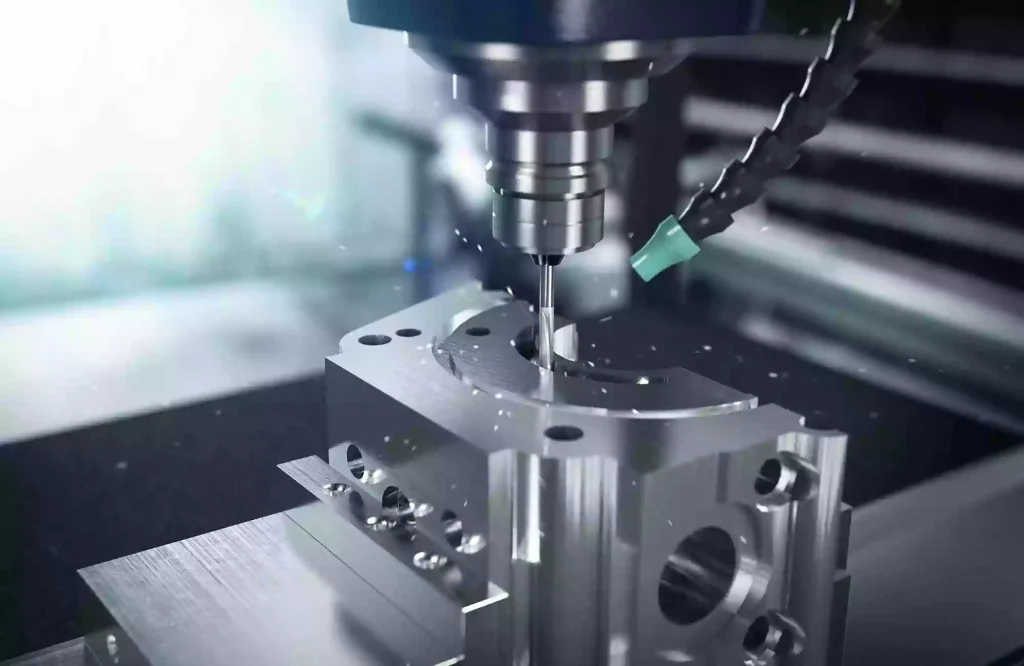
Machining Processes for Complex, High-Precision Aluminum Alloy Thin-Walled Parts
Aluminum alloy thin-walled components are widely used in aerospace and advanced equipment manufacturing because of their low weight, high strength-to-weight ratio, and corrosion resistance. Their lightweight structures help reduce overall equipment weight while maintaining the required mechanical performance. However, machining large components with complex geometries, thin walls, and tight dimensional tolerances presents significant manufacturing challenges.
Unlike conventional aluminum components, thin-walled parts are particularly sensitive to cutting forces, clamping pressure, and changes in internal residual stress. Removing large amounts of material during rough machining can disturb the existing stress balance within the workpiece. Clamping forces may also cause elastic deformation, which can become visible as dimensional deviations or surface distortion once the part is released from the fixture.
For this reason, achieving precision in thin-wall machining requires more than simply reducing cutting depth or adding extra finishing passes. Workpiece preparation, fixture design, machining allowances, heat treatment, and secondary machining operations must be planned as part of an integrated process.
This article examines a machining case involving a complex, high-precision aluminum alloy thin-walled component. It explores how staged milling, stabilization heat treatment, and EDM wire cutting were coordinated to control deformation and improve the final machining quality.
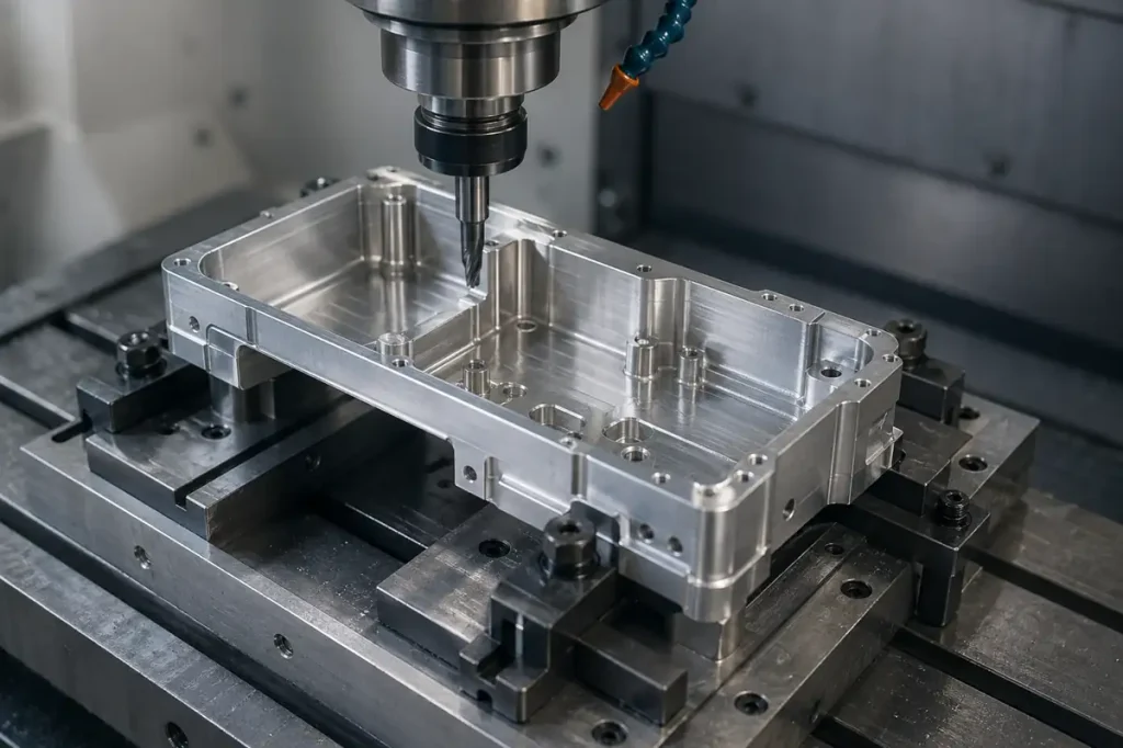
1. Machining Challenges of Aluminum Alloy Thin-Walled Parts
The component in this case was manufactured from 2D14 high-strength aluminum alloy. It featured a relatively large overall size, complex internal cavities, and external contours, with demanding dimensional accuracy and geometric tolerance requirements. Its machining operations primarily involved pocket milling and contour milling.
Several factors made the manufacturing process particularly challenging.
Residual Stress Redistribution
Residual stresses may develop in aluminum alloy stock during earlier manufacturing processes, including rolling, forging, and heat treatment. When substantial material is removed during rough machining, the original stress balance changes. The resulting redistribution can cause bending, twisting, or dimensional shifts.
These effects become more significant in large components with relatively thin walls, where even minor deformation can affect critical dimensions.
Clamping-Induced Deformation
Thin-walled components have limited structural rigidity and often require hold-down clamps, modular fixtures, or custom tooling for secure positioning. Excessive or uneven clamping pressure can deform the workpiece while it is being machined.
Once the clamps are released, the workpiece may partially recover its original shape. This springback can cause the measured dimensions to differ from those obtained during machining.
Reduced Rigidity During Material Removal
As machining progresses, material is progressively removed from the workpiece, changing its stiffness and load-bearing characteristics. Cutting forces, heat generation, and vibration can all affect the stability of thin-wall sections.
Uneven material removal may further increase deformation, particularly when machining deep cavities and narrow structural walls.
To address these issues, the machining strategy in this case focused on workpiece design and process sequencing rather than relying solely on additional finishing operations. Sacrificial clamping extensions, controlled machining allowances, and intermediate stabilization treatments were incorporated into the overall process.
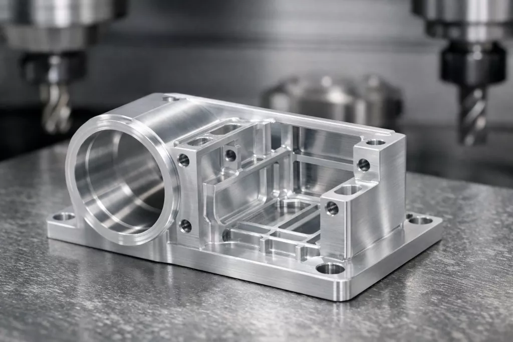
2. Developing the Machining Process for Complex Thin-Walled Parts
The machining sequence was designed to balance material removal efficiency with dimensional stability. Instead of completing the entire component in one continuous milling operation, the process was divided into rough machining, first stabilization treatment, semi-finishing, second stabilization treatment, final machining, and fixture removal.
A key feature of this approach was the use of sacrificial clamping extensions at both ends of the raw material.
2.1 Workpiece Preparation and Clamping Design
Because the component had limited rigidity, directly clamping its final thin-wall sections could introduce localized pressure and deformation.
To avoid this, the raw stock was prepared with additional clamping extensions measuring 30–50 mm at both ends. These extensions provided dedicated clamping areas for the machining operations.
By applying clamping forces to these additional sections rather than directly to the finished component geometry, the workpiece could be secured more reliably while reducing the risk of deformation in the thin-wall areas.
The extensions were temporary manufacturing features rather than part of the finished component. They remained in place throughout milling and were removed after the main cavities and external contours had been completed.
This approach separated the requirements for workpiece holding from those of the final component geometry, allowing the thin-walled structure to remain supported during the earlier machining stages.
2.2 Rough Machining: Removing the Bulk of the Material
The rough machining stage focused on removing excess stock and establishing the basic external profile and internal cavities.
Two-flute carbide end mills with diameters of φ16–φ20 mm were used, with spindle speeds set between 6,000 and 7,000 rpm. The component was secured through the clamping extensions, with 3–5 mm of stock left per side.
At this stage, material removal efficiency was the main priority rather than achieving final dimensions. Retaining sufficient machining allowance provided room for subsequent corrections after stress-relief treatment.
The larger-diameter, two-flute cutters were selected to support efficient material removal during roughing, reducing the amount of stock that would need to be removed during the later finishing stages.
After rough machining, the workpiece underwent the first stabilization heat treatment.
2.3 First Stabilization Heat Treatment
Removing a substantial amount of material during rough machining can disturb the residual stress distribution within an aluminum alloy workpiece. A stabilization treatment was therefore introduced before semi-finishing.
The rough-machined component was placed in an artificial aging furnace, heated to 250–290°C, held at temperature for 2–4 hours, and then allowed to cool in air.
This treatment was intended to relieve part of the residual stress generated or redistributed during material removal, helping reduce dimensional changes in subsequent machining operations.
Positioning the treatment between rough machining and semi-finishing allowed the component to undergo stress relief before its geometry was brought closer to the final dimensions.
2.4 Semi-Finishing: Refining the Geometry and Machining Allowance
After the first stabilization treatment, the component proceeded to semi-finishing.
The objective was to refine the external profile and internal cavities while maintaining sufficient stock for final machining. Compared with roughing, this stage required greater attention to contour accuracy, machining allowance distribution, and the forces applied to thin-wall sections.
Three-flute carbide end mills with diameters of φ10–φ16 mm were used, with spindle speeds ranging from 2,000 to 2,500 rpm. The component remained clamped at both ends, and 0.5–1 mm of stock was retained per side.
Using different cutters for roughing and semi-finishing allowed each stage to address a distinct manufacturing requirement. Roughing prioritized material removal, while semi-finishing focused on correcting the geometry and improving the machined surfaces.
After semi-finishing, the workpiece underwent a second stabilization treatment to further improve its dimensional stability before final machining.
2.5 Second Stabilization Treatment and Final Machining
The second stabilization treatment was performed at 250–290°C, with a holding time of 1–2 hours.
By this stage, the workpiece had already undergone substantial material removal and geometric correction. The additional treatment was intended to further stabilize the material before the final machining operation.
The process also incorporated thermal cycling to help improve dimensional stability. The specific procedure is discussed in the following section.
After stabilization, the component entered the final machining stage. Three-flute carbide end mills with diameters of φ6–φ8 mm were used, with spindle speeds controlled at 1,500–1,800 rpm.
The workpiece was secured using hold-down clamps positioned at the two sacrificial extensions. The remaining stock was then removed to complete the final external contours and internal geometry.
Because the component had already passed through two stages of material removal and stabilization, the final operation focused on achieving the required dimensions and surface quality.
3. Thermal Cycling for Improved Dimensional Stability
In addition to the two stabilization treatments, the machining process incorporated a low-temperature thermal cycling procedure to further improve the dimensional stability of the aluminum alloy component.
Following the second stabilization treatment, the workpiece was placed in a low-temperature chamber maintained at -70 to -50°C for 1–2 hours.
After the low-temperature treatment, the component was removed and allowed to reach a condition suitable for the subsequent heating stage. Once surface frost had melted, it could be transferred to the heating equipment. Alternatively, it could first be dried at approximately 50°C for 1–2 hours.
The component was then heated to the specified temperature, held as required, and allowed to cool to room temperature. Depending on the machining requirements, the low-temperature and heating stages could be repeated for the specified number of cycles.
Liquid nitrogen could also be used to achieve the low-temperature condition. According to the original case, the cooling rate during this treatment did not have a substantial effect on the thermal cycling results.
If immediate heating was not possible after the low-temperature stage, an interruption of up to 20 hours was permitted under the reported process conditions.
It is important to note that thermal cycling is not a universal requirement for every aluminum alloy component. Its suitability, temperature range, holding time, and number of cycles should be established according to the alloy grade, initial material condition, and applicable heat-treatment specifications.
4. Cutting Tool Selection and Machining Parameters
Tool selection and cutting parameters have a direct influence on material removal efficiency, cutting loads, and final surface quality.
Rather than using the same cutter throughout the entire operation, this case employed different tool diameters, flute configurations, and spindle speeds for each machining stage.
| Machining stage | Cutting tool | Spindle speed | Stock allowance per side |
| Rough machining | 2-flute, φ16–φ20 mm | 6,000–7,000 rpm | 3–5 mm |
| Semi-finishing | 3-flute, φ10–φ16 mm | 2,000–2,500 rpm | 0.5–1 mm |
| Final machining | 3-flute, φ6–φ8 mm | 1,500–1,800 rpm | Final dimensions |
Each tool configuration served a different purpose.
During rough machining, the larger two-flute cutters supported the removal of substantial amounts of material. The subsequent three-flute cutters were used to refine the component geometry and complete the finishing operations.
Dividing the work into separate machining stages helped prevent excessive material removal and final dimensional control from becoming competing requirements within a single operation. It also provided opportunities to stabilize the workpiece between major machining stages.
However, spindle speed alone does not determine machining performance. Feed rate, cutting depth, tool overhang, cutter geometry, and machine rigidity must also be considered when developing a practical cutting strategy.
The parameters listed above reflect the specific conditions of this machining case and should not be treated as universal settings for all aluminum alloy thin-walled components.
5. EDM Wire Cutting for Sacrificial Fixture Removal
Once the internal cavities and external contours had been completed, the sacrificial clamping extensions at both ends still needed to be removed.
At this stage, the component had already reached its thin-walled final geometry. Using conventional milling to remove the extensions could introduce additional cutting forces and potentially affect the dimensional stability of the finished structure.
EDM wire cutting was therefore selected for the final separation operation.
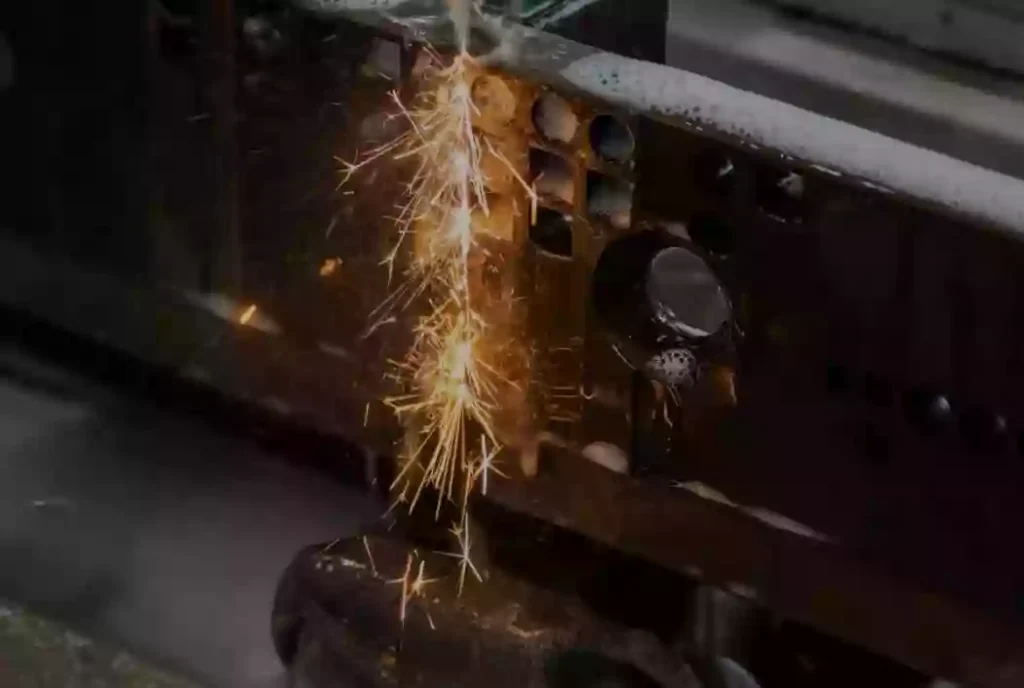
Wire EDM removes material through controlled electrical discharges between a wire electrode and the workpiece. Since it does not rely on direct mechanical cutting contact, it avoids the significant cutting forces associated with conventional milling.
This makes it a suitable option for removing temporary connections from thin-walled structures when mechanical loading needs to be minimized.
The case used the following electrical discharge parameters:
- Polarity: Positive polarity, with the workpiece connected to the positive terminal and the wire electrode connected to the negative terminal.
- Machining current: 3–5 A.
- Pulse duration: 30–50 μs.
- Duty ratio: 1:7 to 1:5.
After wire cutting, visible discharge marks could remain at the separation points between the workpiece and the sacrificial extensions. Fine sandpaper was used to polish these areas and improve the continuity of the finished surface.
Although wire EDM reduces mechanical cutting forces, the discharge process still generates localized heat and may affect the surface layer. Cutting parameters, workpiece support, and subsequent surface finishing therefore remain important considerations.
6. Machining Results and Expert Insights
The main improvement in this case came from coordinating the individual manufacturing operations rather than relying on a single machining technique.
The sacrificial extensions provided stable clamping areas during rough machining, semi-finishing, and final machining. Two stabilization treatments were incorporated after substantial material removal to reduce the influence of residual stress redistribution on subsequent operations.
Different cutting tools and parameters were selected for each machining stage, while EDM wire cutting was used to remove the sacrificial extensions after the main geometry had been completed.
According to the reported machining results, this process effectively controlled dimensional changes associated with machining stress and clamping, while also reducing workpiece transfers between operations and improving overall production efficiency.
Expert Insights
The key value of this approach lies in adapting the machining sequence to the component’s actual structural characteristics rather than relying solely on higher-end machine tools or additional finishing passes.
The combination of sacrificial clamping extensions, staged material removal, and intermediate stabilization treatments helped address deformation throughout the manufacturing process. EDM wire cutting provided a further advantage by minimizing mechanical loading during the final removal of the temporary fixture sections.
For complex, high-precision thin-walled components, machining quality depends not only on the capability of individual operations but also on how the entire manufacturing sequence is organized. Fixture design, residual stress management, cutting strategy, and final separation methods must work together to achieve dimensional stability.
7. Aluminum Thin-Wall CNC Machining at Xtmade
Manufacturing complex aluminum thin-walled components requires careful evaluation of the customer’s existing design, particularly when parts include intricate cavities, thin structural sections, and tight geometric tolerances.
At Xtmade, we provide custom aluminum CNC machining services based on customer-supplied engineering drawings, CAD files, or samples. Our engineering team reviews part geometry, machining allowances, fixture requirements, and tool accessibility through DFM assessments before production.
Our 120,000 sq. ft. manufacturing facility in Shenzhen is equipped with 3-axis, 4-axis, and 5-axis CNC machining centers to support components with complex geometries and precision requirements.
For custom aluminum machining projects, we support standard tolerances of ±0.01 mm and precision machining tolerances of ±0.005 mm, subject to part geometry, material conditions, and manufacturing requirements. CMM inspection and other appropriate measurement methods are used to verify critical dimensions and geometric features.
From prototypes to production runs, we work with customers to establish practical machining processes that balance dimensional accuracy, structural stability, and manufacturing efficiency.
Have a complex aluminum thin-walled component to manufacture? Send your drawings or CAD files to Xtmade for an engineering review and custom machining quote.
Conclusion
Machining complex, high-precision aluminum alloy thin-walled components requires a coordinated approach to material removal, stress management, and workpiece support.
This case demonstrates how sacrificial clamping extensions, staged milling, stabilization heat treatments, thermal cycling, and EDM wire cutting can be combined into a structured manufacturing process. Rather than depending entirely on machining equipment or repeated finishing operations, the process addresses deformation risks at different stages of production.
The specific parameters and treatment conditions must be adapted to the material grade, component geometry, dimensional requirements, and available equipment. When these factors are considered together, a well-planned machining sequence can help improve dimensional stability, surface quality, and production efficiency.