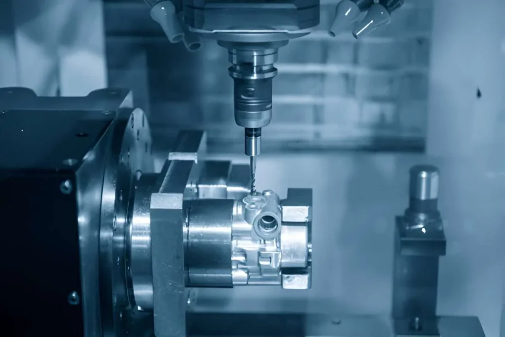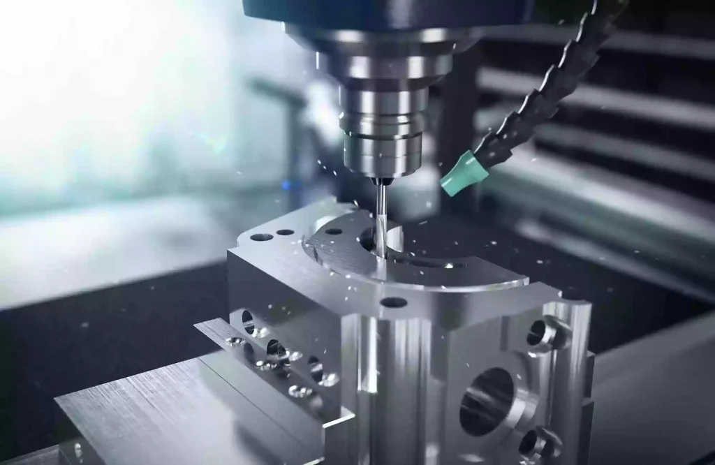
Process Characteristics and CNC Machining Challenges for Precision Aerospace Cylindrical Components
Precision aerospace cylindrical components typically feature complex, non-standard geometries, thin-walled structures, and an array of precision-engineered holes. Their manufacturing process encompasses a wide range of factors, including material properties, structural rigidity, machining accuracy, and the coordination of multiple operational stages. Components fabricated from high-strength alloy steels—such as 35CD4—present particular challenges: they are subject to high cutting forces, elevated temperatures, and accelerated tool wear, while also being highly susceptible to deformation caused by cutting forces, clamping stresses, and thermal effects.
Furthermore, the precision external surfaces, deep holes, inclined holes, and bearing bores on these components often carry distinct dimensional and geometric tolerance requirements. Certain areas may also necessitate specialized surface treatments, such as shot peening, chrome plating, cadmium plating, or painting. Consequently, the manufacturing process must account not only for the precision of individual operations but also for the dimensional relationships between various features, as well as the impact of downstream processes on the final quality of the component.
Taking 35CD4 alloy steel precision aerospace cylindrical components as a case study, this article analyzes the manufacturing challenges and key process control points for such complex, thin-walled parts—covering aspects from structural design and material machining characteristics to critical manufacturing processes and specialized surface treatments. Additionally, drawing on Xtmade’s expertise in the CNC precision machining of complex structural components, multi-axis machining, and quality inspection, this article explores the interplay between process planning and manufacturing capabilities in the production of precision parts.
Structural and Technological Characteristics of Precision Aerospace Cylindrical Components
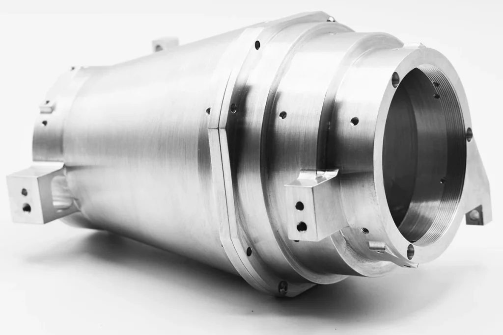
Precision aerospace cylindrical components are generally not simple solids of revolution; rather, they are complex, non-standard parts comprising a main cylindrical body, localized lugs, connecting structures, and internal hole patterns. The challenges in their machining stem not only from the irregularity of their external geometry but also from factors such as localized wall thickness, structural rigidity, the distribution of hole patterns, and the dimensional relationships between various machined features.
For such components, the machining process must simultaneously account for the dimensional accuracy of both external and internal surfaces, the positional relationships between different hole patterns, and the risk of deformation in localized thin-walled areas. In particular, when dealing with multi-stage and multi-directional machining, the strategic selection of machining datums and the optimal sequencing of operations are critical factors that directly influence the final dimensional stability and geometric precision of the component.
Structural Characteristics of Components
Precision cylindrical components in the aerospace sector typically exhibit the following structural characteristics:
Complex External Geometry
While the main body of the component is cylindrical, its exterior may feature lugs, mounting bases, connecting bosses, or other irregular structures. These localized features complicate the clamping and positioning of the part, while also posing challenges regarding tool accessibility and the potential for interference during machining.
Thin-Walled Sections and Non-Uniform Wall Thickness
To minimize weight while maintaining structural integrity, these cylindrical components often incorporate thin-walled sections, with wall thicknesses that can vary significantly across different areas. Such thin-walled regions lack sufficient rigidity and are prone to elastic deformation under the influence of cutting and clamping forces. Furthermore, “spring-back” may occur upon the release of these forces, potentially compromising the consistency of outer diameters, inner bores, and wall thicknesses.
Diverse Hole Configurations
The internal structure may comprise a variety of features, including deep axial holes, inclined holes, connecting holes, and precision bearing bores. These holes have distinct requirements regarding diameter, depth, machining orientation, and positional accuracy. Some may also necessitate significant tool overhang, which increases the difficulty of both machining and inspection.
Multiple Machined Surfaces and Mating Features
The outer surfaces, inner bores, and specific bearing holes of a cylindrical component often serve distinct functions—such as positioning, connecting, or mating—thereby necessitating high standards for dimensional accuracy, surface roughness, and geometric tolerances. Additionally, certain surfaces may require post-machining treatments such as plating, shot peening, or painting, which impose further requirements regarding machining allowances and surface protection.
Critical Dimensions and Precision Requirements
Compared to standard cylindrical components, the dimensional control of precision aerospace cylindrical parts often involves multiple interrelated machining features. Taking the 35CD4 alloy steel cylindrical component analyzed in this text as an example, the primary precision requirements are focused on the following areas:
Precision External Surfaces
The external surfaces at the ends of the cylinder are subject to strict diameter tolerances, while the wall thickness in these regions is only approximately 2.81 mm. Due to this thin-walled nature, factors such as clamping forces, cutting forces, and temperature fluctuations during the turning process can significantly affect the external dimensions and roundness.
Deep Internal Bores
The component features a deep axial bore with a length of approximately 287.5 mm. In addition to the bore diameter tolerance, it is necessary to control the coaxiality between the internal bore and the external surface, as well as the cylindricity of the bore itself. The depth of the hole, tool overhang, and chip evacuation conditions all influence the final machining quality.
Inclined Holes
An inclined hole, positioned at a 45° angle relative to the main axis, is located within a lug on the component. This configuration imposes stringent requirements on angular positioning, tool length, machine tool working envelope, and the avoidance of interference between the tooling and the fixtures.
Precision Bearing Bores
The bearing bores located within the lugs are precision-fit features. Due to the rigidity of the local structure and the required machining orientation, some operations necessitate a significant tool overhang. During machining, it is essential to ensure not only the correct bore diameter but also the roundness, positional accuracy, and surface quality.
Overall, the machining precision of such components is not determined by any single dimension in isolation; rather, it depends on the complex dimensional relationships between the external surfaces, internal bores, inclined holes, and various connecting features. Any deformation or positioning deviation introduced during a single operation can potentially compromise the precision of subsequent machining features.
Material Characteristics and Machining Challenges of 35CD4 Alloy Steel
Material properties are a critical factor influencing the manufacturing processes for precision cylindrical components in the aerospace sector. 35CD4 is a nickel-chromium-molybdenum alloy structural steel characterized by high strength, excellent toughness, and good hardenability, making it well-suited for mechanical components that require high load-bearing capacity and structural reliability.
However, these advantageous properties also make the material more difficult to machine. In particular, when processing thin-walled cylinders, deep holes, or precision hole patterns, factors such as high cutting forces, significant heat generation, and tool wear can adversely affect both machining efficiency and dimensional stability. Consequently, a thorough understanding of the material’s chemical composition, heat-treatment state, and cutting characteristics is essential before developing any machining process.
Chemical Composition and Mechanical Properties of 35CD4
35CD4 is a medium-carbon alloy structural steel whose main alloying elements include carbon, chromium, nickel and molybdenum. Together, these elements affect the material’s strength, hardness, toughness and heat-treatment response.
The main effects of each alloying element are as follows:
| Alloying Element | Main Effect on Material Properties |
| Carbon (C) | Increases strength and hardness; affects hardenability |
| Chromium (Cr) | Improves hardenability, wear resistance and strength |
| Nickel (Ni) | Improves toughness, especially low-temperature toughness |
| Molybdenum (Mo) | Improves hardenability and temper resistance; improves performance at high strength levels |
The properties of 35CD4 are closely tied to its heat-treatment condition. Different treatments, such as normalizing and tempering or quenching and tempering, produce different strength and hardness levels to meet the service requirements of the part.
For CNC machining, machinability cannot be judged from the material grade alone. The tools and cutting parameters should be chosen based on the actual hardness, heat-treatment condition, microstructure of the blank, and the machining allowance of the part.
Machining Characteristics of 35CD4 Alloy Steel
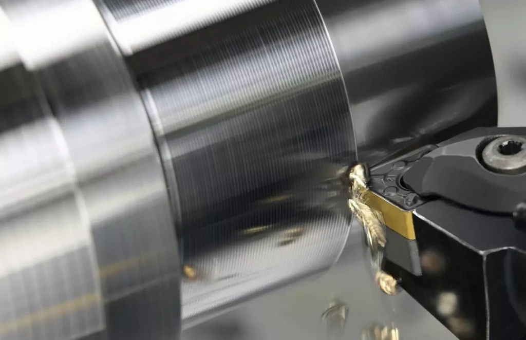
35CD4 alloy steel possesses high strength and toughness, which often leads to significant cutting loads, concentrated heat, and accelerated tool wear during the machining process. The primary challenges in machining this material are outlined below.
High Cutting Forces
Due to its high strength and hardness, the material presents significant resistance to deformation during machining, resulting in relatively high cutting forces. For thin-walled cylindrical components, these high forces not only increase the load on the cutting tool and machine tool but can also cause elastic deformation of the workpiece, thereby compromising dimensional and geometric accuracy.
High Cutting Temperatures
During machining, heat is generated through the plastic deformation of the material, friction between the tool and the workpiece, and contact between the chips and the tool’s rake face. This concentration of heat in the cutting zone can lead to elevated tool temperatures and localized thermal deformation of the workpiece, which in turn affects the precision of external and internal dimensions.
Tendency Toward Work Hardening
The combined effect of cutting forces and heat can induce plastic deformation in the surface layer of the material, resulting in localized hardening. This work hardening increases resistance during subsequent cutting passes, imposes greater loads on the tool, and may negatively impact the quality of the machined surface.
Rapid Tool Wear
High cutting forces and elevated temperatures accelerate tool wear. As the cutting edge becomes dull, cutting forces and heat may increase further, leading to dimensional deviations, increased surface roughness, and reduced machining efficiency. Consequently, it is essential to carefully select tool materials, tool geometry, and cutting parameters based on the material’s hardness and the specific machining conditions.
Difficulties in Chip Management
35CD4 exhibits a degree of plasticity and toughness, which, under certain cutting conditions, tends to produce continuous, ribbon-like chips. If chip breaking is ineffective, these long chips may become entangled around the tool or the workpiece, hindering chip evacuation and cooling, and potentially scratching the machined surface. 6. Risk of Machining-Induced Deformation
Under high cutting loads and thermal effects, workpieces may undergo localized elastic and thermal deformation. Furthermore, the release of inherent internal stresses within the material during rough machining can also lead to changes in the part’s shape. For thin-walled cylindrical structures, these factors further complicate the task of maintaining dimensional control.
Heat Treatment and Pre-machining Process Requirements
For high-strength alloy steel aerospace components, heat treatment not only influences final mechanical properties but also dictates the process planning for subsequent CNC machining.
In the manufacturing process for the cylindrical components discussed here, the forged blanks must undergo appropriate pre-machining before heat treatment. This improves the cross-sectional conditions across the blank, ensuring a more effective and consistent heat treatment process.
Rough Machining Prior to Heat Treatment
Based on the component’s structure and heat treatment specifications, the forged blank undergoes preliminary machining to remove a portion of the excess material (machining allowance) and to control the wall thickness of various cross-sections. In this specific case, the wall thickness at any cross-section is required to be less than 30 mm after rough machining to meet the technical requirements for the subsequent heat treatment.
Establishing Datums Post-Heat Treatment
Since heat treatment can cause changes to a component’s dimensions and shape, the requirements for subsequent positioning must be considered during the rough machining stage. Establishing proper alignment datums on the blank after rough machining facilitates accurate repositioning in later stages, thereby minimizing machining errors caused by datum shifts.
Sequencing Rough and Finish Machining
For cylindrical components featuring thin walls and precise hole patterns, it is not advisable to machine the part to its final dimensions directly from the raw blank. A well-planned sequence—incorporating rough machining, heat treatment, semi-finishing, and finish machining—helps to relieve internal machining stresses and provides the necessary flexibility to achieve final dimensional and geometric tolerances.
In summary, the difficulty of machining 35CD4 alloy steel stems not only from its inherent strength and hardness but also from its heat-treatment state, the component’s structural design, and the amount of excess material to be removed. Only by developing a process that integrates material characteristics with the component’s structural design can one create stable conditions for subsequent precision external cylindrical machining, deep-hole drilling, and the machining of complex hole patterns.
Key Machining Process Characteristics for Precision Aerospace Cylindrical Components
The challenges in machining precision aerospace cylindrical components stem not only from the material’s machinability but also from the component’s structural rigidity, the distribution of its features, and the requirements for dimensional accuracy. Given the thin-walled nature of the main cylindrical body, the complexity of certain localized structures, and the presence of diverse features—such as external cylindrical surfaces, deep holes, inclined holes, and precision bearing bores—the various machining operations can easily influence one another.
In actual manufacturing, it is essential to carefully plan work-holding methods, the sequence of operations, tool selection, and cutting parameters based on the specific structural characteristics of each feature. This is necessary to prevent issues such as localized deformation, tool vibration, or datum shifts, which could otherwise compromise the final dimensional accuracy.
Machining and Deformation Control of Thin-Walled Cylindrical Components
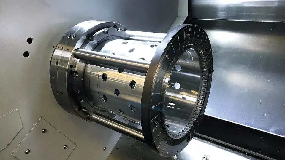
Thin-walled structures are a characteristic feature of precision cylindrical components in the aerospace industry. To meet requirements for lightweight design and structural strength, these components often feature thin walls; however, their limited cross-sectional rigidity makes them highly susceptible to deformation during machining.
Key influencing factors include:
Deformation caused by clamping forces: During turning or milling, thin-walled cylindrical components must be positioned and secured using fixtures. Excessive clamping force or an uneven distribution of force can lead to localized compression or ovality (out-of-roundness). Furthermore, once the component is unclamped following machining, it may undergo dimensional springback.
Deformation caused by cutting forces: Thin-walled sections have a low resistance to cutting loads. When the tool engages with the workpiece, cutting forces can cause the structure to deflect elastically. This results in a discrepancy between the actual depth of cut and the intended value, thereby affecting wall thickness and final dimensions.
Deformation caused by cutting heat: A rise in temperature within the cutting zone can lead to localized thermal expansion. Uneven temperature distribution across different parts of the component often results in thermal deformation, which can compromise the accuracy of outer diameters, inner bores, and other critical dimensions.
Consequently, the machining of thin-walled cylindrical components requires careful consideration of clamping forces, cutting loads, and heat distribution. The risk of deformation during the machining process can be mitigated by optimizing fixture support locations, employing a multi-stage machining strategy, appropriately allocating machining allowances, and strictly controlling parameters during the finishing stages.
Characteristics of Precision External Cylindrical Machining
The outer surface of a cylindrical component typically serves a positioning, assembly, or mating function; consequently, it is subject to stringent requirements regarding diameter, roundness, and surface roughness.
In the case of the component discussed here, the tolerance zone for the outer diameter at the end section is only 0.022 mm, while the corresponding wall thickness is approximately 2.81 mm. This combination of tight dimensional tolerances and thin-walled geometry presents significant process challenges for external cylindrical machining.
First, thin-walled sections are prone to radial deformation during both clamping and cutting. Excessive clamping force can lead to non-uniformity in the machined outer diameter, while insufficient workpiece rigidity during cutting may result in vibration and localized dimensional deviations.
Second, factors such as tool wear, cutting temperature, and the thermal stability of the machine tool can all influence the final outer diameter. When machining high-strength alloy steel, tool wear can alter the actual cutting conditions, making it difficult to maintain dimensional consistency throughout continuous production.
Therefore, precision external cylindrical machining requires a comprehensive approach that accounts for workpiece support, tool condition, cutting parameters, and machining allowance. Furthermore, post-machining dimensional inspection is essential to verify that the diameter and roundness meet the specified requirements.
Characteristics of Deep-Hole Internal Machining
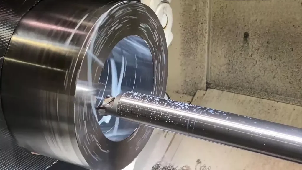
The main difficulties of deep-hole machining are the long tool overhang, the enclosed cutting zone, and relatively limited chip evacuation and coolant conditions. For precision aerospace cylindrical parts, the bore must not only meet the diameter requirement but may also need to maintain a strict concentricity relationship with the outer diameter.
In the original case, the bore depth reaches 287.5 mm, with requirements to control the bore diameter tolerance, 0.04 mm concentricity and 0.02 mm cylindricity. This means the process must not only ensure the bore diameter, but also control axis deviation and changes in bore wall shape over the entire bore length.
Deep-hole machining mainly involves the following problems:
- Insufficient tool rigidity: With a long tool overhang, the tool is prone to bending and vibration under cutting forces.
- Difficult chip evacuation: Chips are not easily cleared in time, which can cause re-cutting, tool wear and scratches on the bore wall.
- Limited cooling: Coolant has difficulty fully reaching the inside of a deep hole, which may raise the cutting temperature.
- Bore axis deviation: Uneven cutting forces, initial positioning errors and uneven blank allowance can all cause the bore axis to deviate from its design position.
- Difficult dimensional inspection: Ordinary measuring methods cannot fully reflect the cylindricity and axis variation along the entire depth of the bore.
To address these problems, an appropriate boring or deep-hole drilling approach should be selected based on bore diameter, bore depth and material condition, with close attention to tool rigidity, chip evacuation path, cooling conditions and the stability of machining datums.
Characteristics of 45° Inclined-Hole Machining
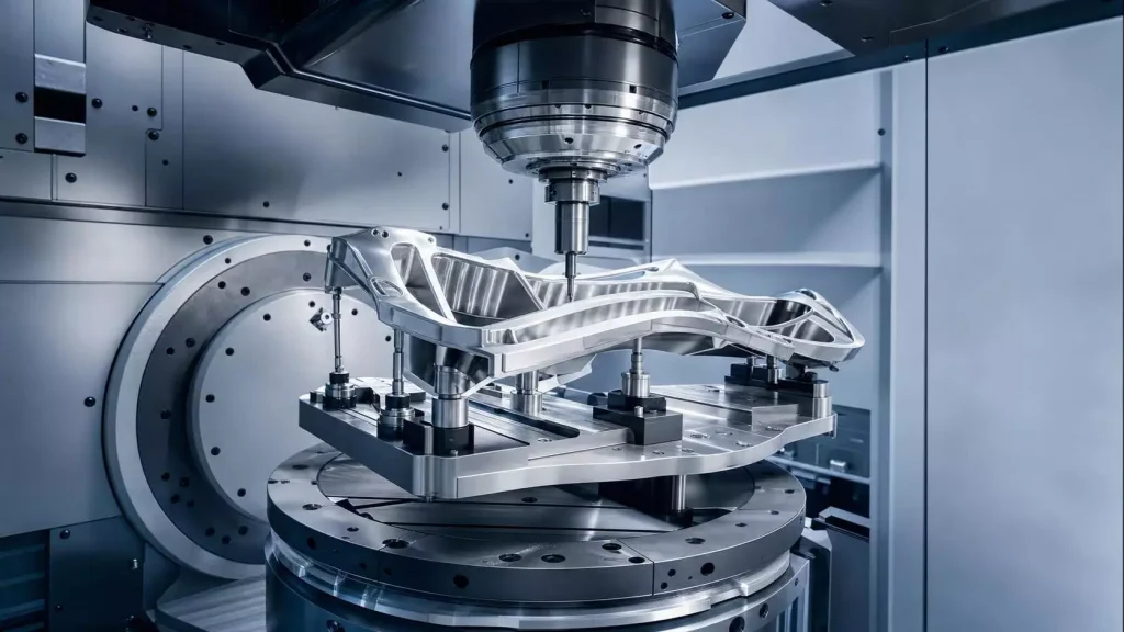
Unlike conventional hole patterns distributed along the cylinder axis, an inclined hole is machined at an angle to the main axis of the part. This places higher demands on machine positioning, tool accessibility and machining space.
In the original case, the inclined hole is located on a local lug of the part, at a 45° angle to the cylinder axis. Because other structures surround the lug, conventional tools and fixtures may interfere with the part, so the machining orientation and tool overhang length must be carefully considered.
The main process difficulties include:
- Angular positioning accuracy: The angular relationship between the inclined-hole axis and the part datums must be established accurately. Positioning errors affect not only the inclination angle of the hole, but may also shift the hole position.
- Tool overhang and rigidity: Due to limited machining space, the tool may need a long-overhang configuration. Greater overhang reduces tool-system rigidity and easily leads to vibration and bore diameter deviation.
- Tool interference: The lug around the inclined hole, the cylinder profile and the fixture structure may restrict tool movement. Interference between the tool, workpiece and fixture should be checked during process planning.
- Multi-axis machining and positioning scheme: Depending on the part structure, 4-axis or 5-axis CNC machining, or a dedicated angle fixture, can be used to keep the tool axis in a suitable position relative to the hole to be machined. The specific scheme should be determined based on the hole position, tool length and machine travel range.
Characteristics of Precision Bearing-Bore Machining
A bearing bore is typically a precision feature with demanding fit requirements. Its diameter, roundness, cylindricity and positional accuracy directly affect subsequent bearing assembly and operating condition.
In the cylindrical part discussed here, the bearing bore is located on a local lug. Constrained by the part’s shape and machining direction, it can only be machined from the left end face of the part. This single-side access requires the tool to have a long overhang, which also increases the risk of vibration and deflection during machining.
In addition, the joint area between the lug and the main cylinder body may have uneven rigidity, making local deformation likely under cutting forces. If tool rigidity is insufficient or the machining allowance is poorly distributed, this may also cause uneven bore diameter and reduced surface quality.
Therefore, bearing-bore machining requires particular attention to:
- Machining datums and positioning method.
- Tool overhang length and system rigidity.
- Control of bore diameter, roundness and cylindricity.
- Positional relationship between the bearing bore and other structural features.
- Dimensional and surface-quality inspection after finishing.
For bearing bores with strict fit requirements, fine boring, reaming or other suitable finishing processes may also be needed, where necessary, to meet the final accuracy specified on the drawing.
Process Coordination Among Multiple Machining Features
The aforementioned machining features are not mutually independent. For instance, there are coaxiality requirements between external cylindrical surfaces and internal bores; the positional relationship between an inclined hole and a bearing bore is influenced by the overall datum system; and machining-induced deformation in thin-walled sections may alter other precision dimensions.
For precision cylindrical components in aerospace applications, optimization cannot be performed for individual operations in isolation. Instead, the entire process route must be considered to coordinate datums, machining sequences, and the allocation of machining allowances across various features. Particular attention must be paid to stress relief following rough machining, the restoration of datums after heat treatment, and the repeatability of positioning when machining from different orientations. Through systematic process planning, it is possible to minimize the accumulation of errors—such as those arising from datum shifts or repeated clamping—thereby ensuring the control of final dimensions and geometric tolerances.
Special Process Requirements for Precision Aerospace Cylindrical Components
The manufacturing of precision aerospace cylindrical components involves not only standard machining operations—such as CNC turning, milling, boring, and drilling—but may also require special processes like shot peening, electroplating, and painting to ensure the components meet specific surface performance and operational requirements.
Unlike conventional mechanical parts, these components often feature multiple surface areas with distinct functions. For instance, certain external cylindrical surfaces may require shot peening, precision internal bores might need chrome plating, while other areas could require cadmium plating or painting. Since each process entails different treatment zones, operational parameters, and surface specifications, it is essential to clearly define these zones during the manufacturing process and effectively coordinate the relationship between mechanical machining and surface treatment.
Shot Peening
Shot peening is a surface-strengthening process in which high-speed shot impacts the part surface, causing plastic deformation of the surface layer and forming residual compressive stress. The process is commonly used for metal parts with fatigue-performance requirements.
For precision aerospace cylindrical parts, shot peening must be applied strictly within controlled areas. Because different surfaces serve different functions, not all areas are suitable for peening.
The main process requirements include:
- Peening area control: Clearly identify the outer diameter and any other specified surfaces to be peened according to the part drawing.
- Protection of non-treated areas: Mask precision mating surfaces, bores and other specified areas where peening is not permitted.
- Process parameter control: Determine the peening intensity, coverage and shot specification based on material properties, part structure and technical specifications.
- Post-treatment inspection: Check peening coverage and surface condition to avoid localized over-treatment or missed areas.
For thin-walled cylindrical structures, attention must also be paid to the effect of the peening process on shape stability, so that unsuitable parameters do not cause changes in dimensions or shape.
Chrome Plating
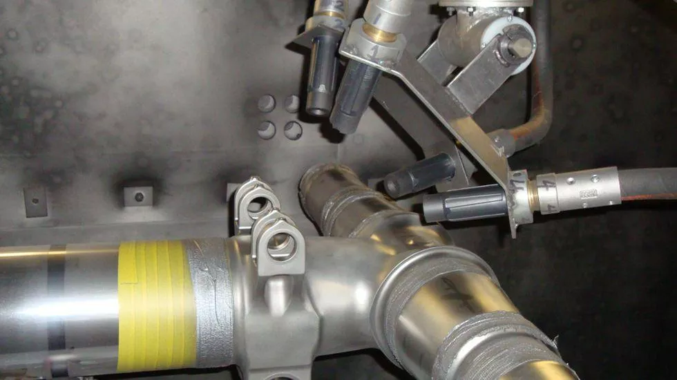
Chrome plating is a surface-treatment process that forms a chromium coating on a metal surface by electrochemical means. Depending on the application, a chromium coating can be used to improve surface hardness, wear resistance and other surface properties.
In the aerospace cylindrical part discussed here, the specified bore requires chrome plating, with a required coating thickness of 20–25 μm.
The main control points of the process include:
- Coating thickness control: Coating thickness directly affects the final bore diameter. The machining allowance must therefore be determined from the pre-plating dimension and the drawing requirements, to avoid an out-of-tolerance bore after plating.
- Coating uniformity: A bore is a relatively enclosed structure, so the effects of current distribution and plating-solution flow on coating uniformity must be considered during plating.
- Pre-plating surface preparation: The machined surface must be properly cleaned and pretreated before plating to ensure good adhesion between the coating and the substrate.
- Post-plating quality inspection: Check coating thickness, surface integrity and final bore diameter as required by the specification, and carry out further finishing if necessary.
For precision bores, coating thickness cannot simply be treated as a single-sided dimensional increase. The final dimensional compensation must be determined according to how the bore is plated and the actual process.
Cadmium Plating
Cadmium plating is a traditional protective process for aerospace and industrial metal parts. It is mainly used to provide a degree of corrosion resistance and to meet surface requirements for specific assembly and service environments.
In the original case, all surfaces other than the specified chrome-plated area are cadmium-plated areas. This multi-zone surface treatment requires the boundaries between the different coatings to be clearly defined at the process planning stage.
The main process requirements include:
- Zone division: Clearly define the boundary between the chrome-plated and cadmium-plated areas to prevent coating on the wrong areas.
- Surface masking: Effectively protect areas where cadmium plating is not permitted.
- Process coordination: Arrange the sequence of chrome plating and cadmium plating sensibly to avoid coating defects at the boundary areas.
- Quality inspection: Check coating coverage, thickness and surface quality.
Note that cadmium carries significant environmental and occupational health risks. The process must be carried out by a qualified supplier with appropriate pollution-control capability, in accordance with applicable specifications, and the availability of alternative protective processes should be evaluated.
Painting
Painting is generally used to improve part appearance, provide surface protection or meet specific coating-performance requirements. For aerospace cylindrical parts with precision mating features, the painted areas must be strictly controlled according to the drawing.
The main process difficulty lies in coordinating the coating coverage with precision dimensions.
First, the areas of the outer diameter where painting is permitted must be clearly defined, and precision surfaces where painting is not permitted must be masked, to prevent paint from entering the bore, mating surfaces and other functional areas.
Second, coating thickness affects the final dimensions of the part. If a painted area is adjacent to a precision outer diameter, the coating thickness and masking boundaries must be considered in advance to prevent paint buildup from affecting assembly.
Finally, after painting, the coating should be checked for complete coverage, adhesion and surface appearance to ensure it meets the part’s technical requirements.
Coordination of Multiple Surface Treatments
When a single precision aerospace part requires several treatments, such as shot peening, chrome plating, cadmium plating and painting, process management becomes even more complex.
The different treatments not only work by different mechanisms but may also affect other surface areas. For example, a clear boundary is needed between chrome-plated and cadmium-plated areas, painted areas must be protected from the plating operations, and precision bores require control of coating thickness and final bore diameter.
Therefore, the coordination of multiple surface treatments should focus on the following aspects:
| Control Item | Main Process Requirement |
| Treatment areas | Define the extent and boundaries of each surface treatment |
| Masking and protection | Protect precision surfaces where treatment is not permitted |
| Process sequence | Coordinate the order of shot peening, plating and painting |
| Dimensional compensation | Account for the effect of plating and coating on final dimensions |
| Final inspection | Inspect coatings and critical dimensions after treatment |
In addition, surface treatment of aerospace parts is usually governed by specific technical specifications. The actual process sequence cannot be determined from general experience alone and must be confirmed against the part drawing, material requirements, applicable standards and the process capability of the treatment supplier.
Quality Inspection and Accuracy Control
Quality control of precision aerospace cylindrical parts cannot rely on final inspection alone. It needs a plan that runs through the whole process and accounts for part structure, datums, geometric tolerances and surface treatments.
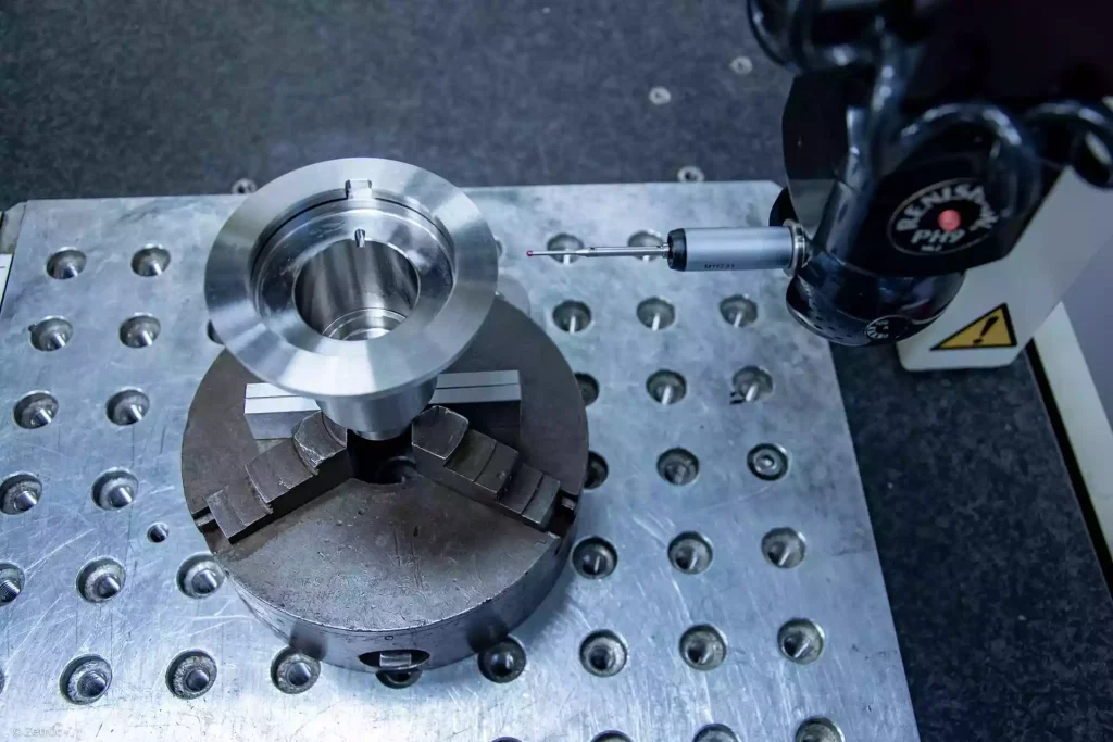
Dimensional and Geometric Inspection
Because the part has thin walls, a deep hole, an inclined hole and lugs, each feature needs its own method. Precision outer diameters can be checked with micrometers, comparators or dedicated fixtures, with measuring force controlled to avoid deforming thin walls. For the 287.5 mm deep bore, an entrance-only measurement is not enough. An internal-diameter comparator, air gauge or long-rod tool should be used at several axial positions, and the 0.04 mm concentricity and 0.02 mm cylindricity should be judged from multi-section data using a CMM, roundness tester or dedicated device. The bearing bore on the lug needs roundness, cylindricity, axis direction and position checked against the datums, and the 45° inclined-hole axis needs its spatial direction and position verified on the CMM. Ideally the outer diameter, end face and bores are measured in one CMM coordinate system to confirm datum transfer. The method must match the tolerance definition on the drawing, since concentricity, position and cylindricity are evaluated differently, and probe access and measurement paths should be planned in advance.
Surface Treatment Inspection
After treatment, inspection extends to coating quality and final dimensions. Chrome-plated bores need thickness and coverage checks and must be re-measured after plating, because the final size is based on the post-plating result. Cadmium plating and paint are checked for coverage, thickness, adhesion and boundaries, ensuring mating surfaces that must stay bare are unaffected. Shot peening is evaluated for coverage, intensity and treated area per the specification, along with any dimensional or shape change on thin walls.
In-Process Control
Inspection should be placed at key milestones rather than concentrated at the end. Allowances, datums and deformation are checked after rough machining, and datums and critical dimensions are reconfirmed after heat treatment, adjusting later allowances if needed. During finishing, a unified, traceable datum system reduces errors from repeated clamping, and first-article and in-process inspection catch tool wear and clamping deviation. After surface treatments, dimensions, tolerances and surface quality are re-inspected, and final inspection covers all critical items with records and reports as the customer requires.
The aim is not just to judge whether the final part passes, but to find error sources early and stop deviations from accumulating across operations.
Complex Precision Part Manufacturing Support from Xtmade
Founded in 2024 in Shenzhen, China, Xtmade is an ISO 9001-certified custom CNC precision machining manufacturer serving overseas customers. The company was started by a core team of five specialists, led by engineers with more than 20 years of manufacturing experience, and has grown to a team of 70 operating from an 80,000 sq ft factory. We produce custom parts from our customers’ own designs, from prototypes to production runs, including complex, tight-tolerance parts such as thin-walled housings and multi-axis components.
Every order starts with a review of your drawings, CAD files and specifications. Our engineers run DFM analysis and plan the process before production, so potential issues are found early. Parts are then machined and inspected in-house with CMM and other equipment, with first-article, in-process and final inspection.
What we offer:
- CNC machining: 3-axis, 4-axis and 5-axis precision machining
- Complex parts: Thin-walled structures, deep holes, inclined holes and precision bores
- Multi-process manufacturing: Die casting, injection molding and sheet metal
- Engineering support: Drawing review, DFM feedback and quotation
Send us your CAD drawings, specifications or samples, and we will provide a manufacturing plan and quote.
Conclusion
The difficulty of manufacturing precision aerospace cylindrical parts comes from the interaction of complex structure, material properties, thin-wall deformation, precision holes, geometric tolerances and special surface treatments, not from any single operation. For high-strength steels such as 35CD4, machining, heat treatment and surface treatment must be planned together, with unified datums, sound clamping and targeted inspection to control the relationships between features.
For a manufacturer, the key is not just machining individual features, but understanding the drawing, identifying risks, coordinating operations and ensuring quality through in-process inspection.