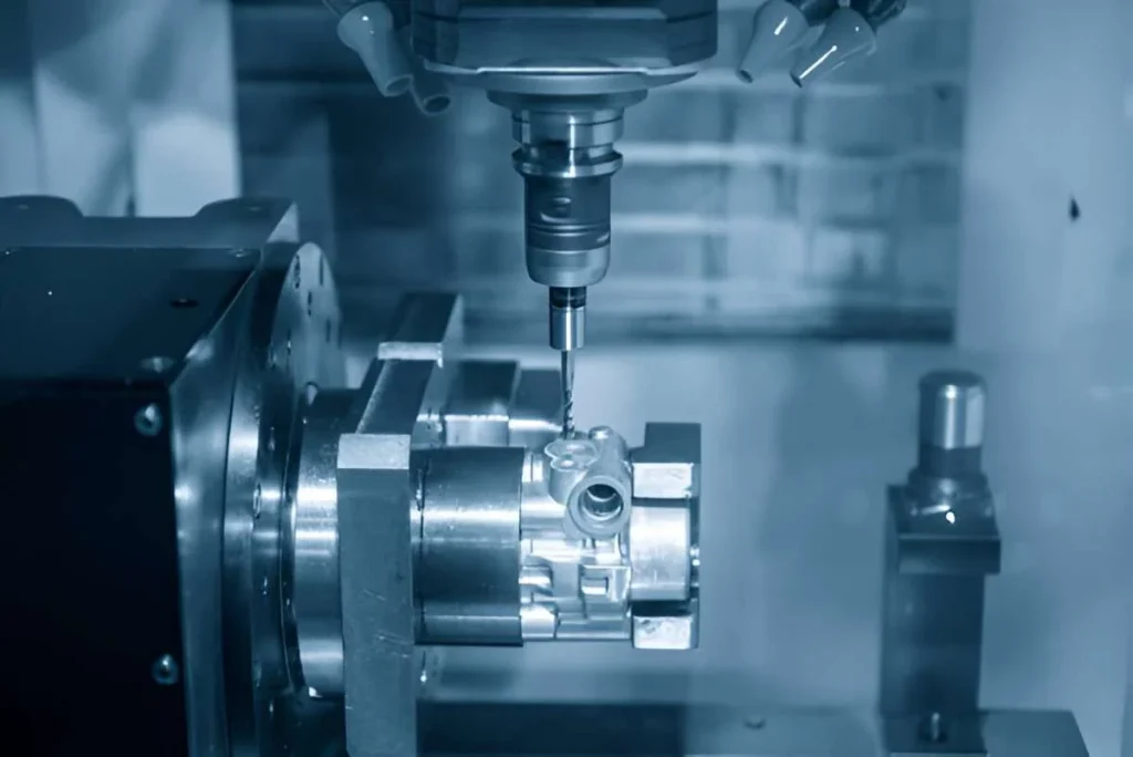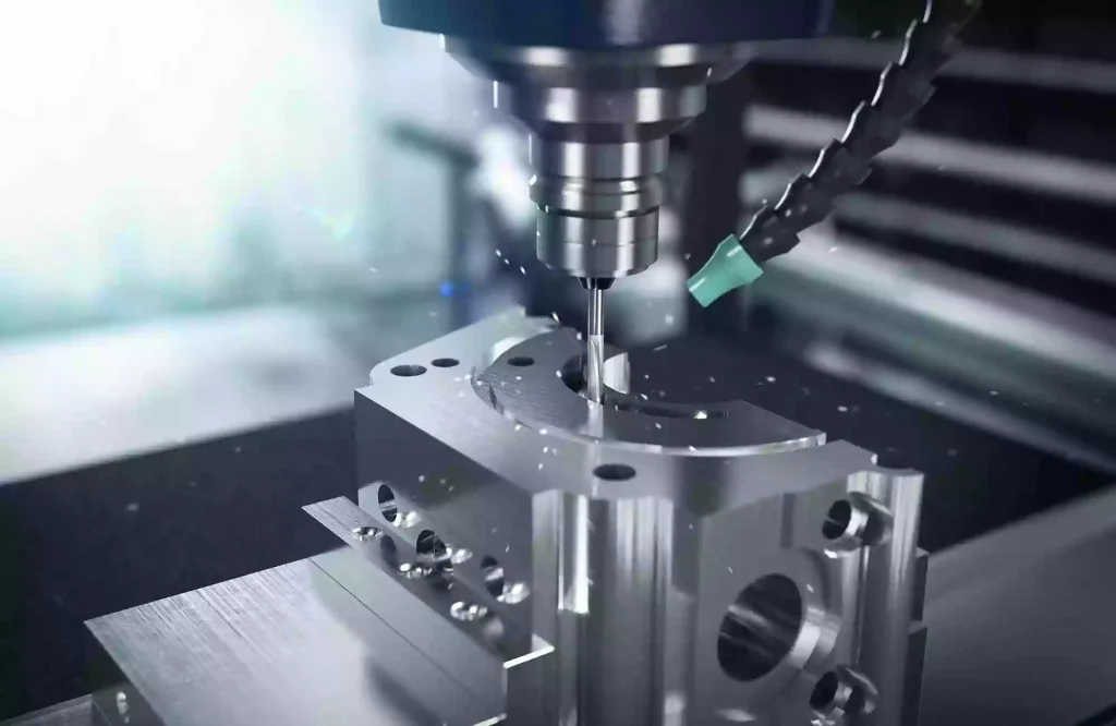
CNC Machining Process Optimization for an Aerospace Precision Cylinder
Aerospace precision cylinder components often feature complex geometries, tight dimensional tolerances, and stringent surface finish requirements. During manufacturing, factors such as material machinability, workholding references, tool rigidity, and process sequencing can all affect the final machining quality.
A 35CD4 high-strength steel aerospace cylinder is a typical example. Its manufacturing process involves precision outer diameter turning, deep-hole boring, extended angled hole milling, and shot peening. Due to the material’s strong tendency to adhere to cutting tools, conventional machining methods may encounter difficulties in maintaining dimensional stability, achieving the required surface quality, and ensuring effective chip evacuation.
For a closer look at the component’s structural characteristics, material properties, and key manufacturing challenges, see our previous article on Process Characteristics and CNCMachining Challenges forPrecision Aerospace CylindricalComponents.
Building on that analysis, this article examines the actual production process, focusing on common machining problems in outer diameter turning, internal bore machining, complex hole features, and shot peening. It also explains how tool selection, cutting parameter adjustments, datum corrections, and process optimization can improve machining quality.
Machining Process Design for an Aerospace Precision Cylinder
Machining an aerospace precision cylinder requires careful control of the dimensional relationships between multiple precision features. A process plan cannot be developed around individual features in isolation. This is particularly important for components containing thin-wall sections, deep bores, and irregular holes, where the condition of previously machined surfaces directly affects the accuracy of subsequent operations.
Based on the component’s geometry and technical requirements, the overall process design focuses on four main areas:
- Machining datums and workholding: Select appropriate locating datums according to the component structure to control clamping errors and rotational deviations during machining.
- Precision feature machining: Develop suitable machining methods and stock allowances for critical outer diameters, internal bores, bearing bores, and extended angled holes.
- Tooling and cutting parameters: Select suitable tool geometries based on the cutting characteristics of 35CD4 steel, then optimize cutting parameters through machining trials.
- Special process sequencing: Consider the dimensional changes that may result from shot peening and arrange finish machining and surface treatment in an appropriate sequence.
By evaluating the interactions between different operations, an overall machining route can be established and continuously refined based on actual production results during trial manufacturing.
Precision Outer Diameter Turning Optimization
Improving Outer Face Surface Quality
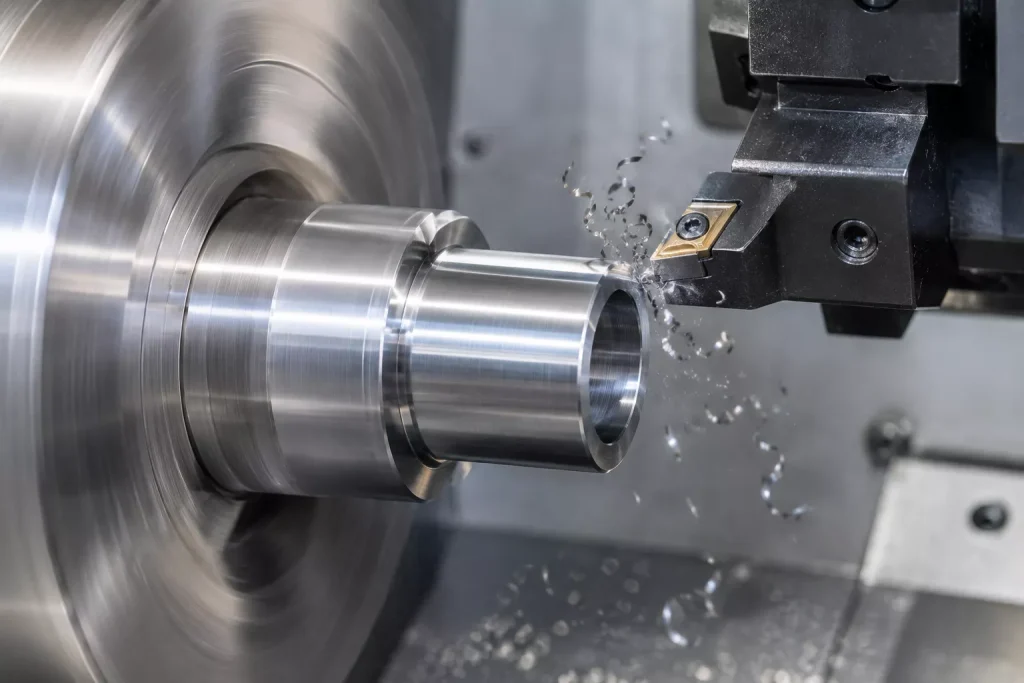
During finish machining of the lug outer diameter and end face, the strong cutting adhesion tendency of 35CD4 steel made chip breaking difficult. Under the original, relatively low cutting parameters, deep cutting marks appeared on the component’s end face, with localized material tearing in some areas.
To address this problem, the outer diameter turning parameters were adjusted, with particular attention to cutting conditions and tool performance. After optimization, the original cutting marks were eliminated, producing a smoother end-face surface with consistent machining quality from the center to the outer edge.
This improvement demonstrates that when machining high-strength steels with strong cutting adhesion tendencies, end-face quality depends not only on the cutting tool itself but also on the cutting parameters and actual cutting conditions. Machining trials and adjustments should be based on the material’s characteristics rather than simply adopting parameters commonly used for conventional steels.
Improving Precision Outer Diameter Dimensional Stability
The CNC turning operation at Process No. 14 was a critical stage in manufacturing this component. A self-centering chuck was used for clamping, while a steady rest supported the outer diameter to improve rotational stability during machining.
The precision outer diameter had a dimensional tolerance of 0.024 mm and required three turning passes. Considering the cutting characteristics of 35CD4 steel, a sharp external turning insert was selected, preferably with an R0.2 mm nose radius. An excessively large nose radius could negatively affect the cutting conditions and surface roughness.
Initial machining trials showed that the finished outer diameter ranged from 88.85 to 88.89 mm, failing to meet the drawing requirements. Before the cause of the dimensional deviation was identified, the production team could only leave additional machining allowance and correct the dimensions through manual polishing.
Further investigation revealed that the problem was closely related to the roundness of the outer diameter supported by the steady rest. The roundness of the support surface affects the component’s rotational condition after clamping. This influence becomes particularly significant when tight dimensional tolerances are required.
Measurements of the support surfaces on nonconforming components showed roundness variations of 0.020–0.035 mm, which were generally consistent with the variation range observed in the finished outer diameter.
The preceding datum machining operation was therefore revised. A roundness requirement of no more than 0.01 mm was added to the outer diameter turning requirements at Process No. 11.
After introducing this roundness control requirement, the stability of the outer diameter turning operation at Process No. 14 improved significantly. The final diameter range narrowed to 88.865–88.875 mm, keeping dimensional variation within 0.01 mm. The drawing requirements could now be met without additional localized manual correction.
Stability trials further confirmed that one cutting edge could consistently machine four components. The tool needed to be replaced after wear to maintain dimensional accuracy.
Internal Bore Machining Process Optimization
Eliminating the Bottom-Face Protrusion
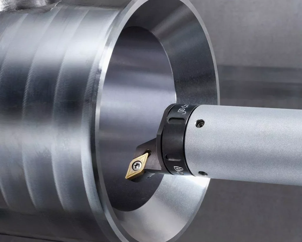
During the CNC turning operation at Process No. 14, a localized protrusion remained at the bottom of the internal bore. The residual feature had a diameter of approximately 1 mm and a height of approximately 0.3 mm.
The original machining process used a flat-bottom milling cutter to remove the excess material at the bottom, followed by internal boring with a large-diameter boring tool. The bottom face was then machined to blend with the surrounding surface.
This approach required tool runout to be controlled within 0.01 mm. However, the flat-bottom milling cutter had a slight angled section at its bottom. Even with controlled tool runout, it was difficult to achieve a completely flat surface, leaving the protrusion defect unresolved.
To address this issue, the original flat-bottom milling operation was replaced with boring using a small-diameter boring tool. This allowed the remaining material at the bottom of the bore to be machined directly.
Machining trials confirmed that boring the bottom surface with the revised tool could completely eliminate the residual protrusion and improve the machining quality of the internal bore’s bottom face.
Improving Internal Boring Quality
At Process No. 14, internal boring had to leave a radial allowance of 0.05 mm for the subsequent honing operation. However, several quality defects appeared in the internal bore during initial production, increasing the machining risks for the subsequent honing process.
Based on the actual machining conditions, three main causes were identified:
- Insufficient tool rigidity: The original internal boring tool had a relatively small diameter and insufficient rigidity. This made it more susceptible to vibration, affecting bore dimensional stability.
- Poor chip evacuation: The strong adhesion tendency of 35CD4 steel made chip breaking difficult. Chips could curl inside the bore and scratch the already machined surface.
- Unsuitable cutting parameters: The original cutting speed was relatively low and did not adequately support the required dimensional accuracy and surface finish.
Three main improvements were introduced to address these problems:
- Replace the original tool with a larger-diameter internal boring tool to increase rigidity and reduce machining vibration.
- Increase the cutting speed and appropriately increase the finishing depth of cut to improve cutting conditions and chip breaking.
- Optimize the internal coolant delivery system so that coolant reaches the boring tool tip directly, improving cooling and chip evacuation in the cutting zone.
By making coordinated adjustments to tool geometry, cutting parameters, and coolant delivery, the internal boring operation was improved, providing a more stable foundation for the subsequent honing process.
Complex Hole Machining Optimization
Improving Extended Angled Hole Machining
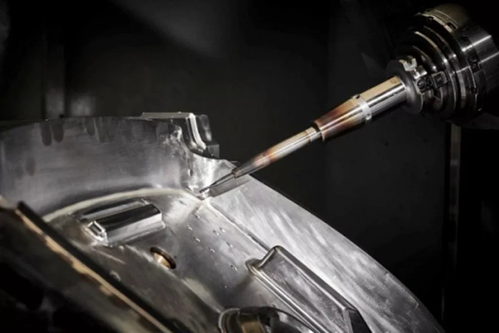
The extended angled hole was machined by horizontal milling at Process No. 13. Due to the considerable hole length and large tool overhang, maintaining stable hole dimensions during machining was challenging.
The initial process used an extended Ø6 mm milling cutter to enlarge the hole to Ø7.3 mm. However, the actual machined diameter was only 7.1–7.2 mm, resulting in dimensional variation of 0.1 mm.
The machining program was subsequently adjusted to increase the target milling diameter to Ø7.5 mm. The actual hole diameter reached 7.35–7.42 mm, but dimensional variation remained at 0.07 mm.
To further improve hole accuracy, a straight-shank reamer was tested for finishing. The resulting hole diameter ranged from 7.62 to 7.69 mm, and dimensional stability remained unsatisfactory.
In the first process adjustment, the reamer was replaced with a boring tool. However, the resulting hole diameter ranged from 7.60 to 7.72 mm, exceeding the tolerance requirements and causing the components to be scrapped.
After comparing and validating several tooling options, a variable-diameter milling cutter with a 7 mm cutting diameter was finally selected for the angled hole machining operation. Following this optimization, the machining acceptance rate reached 100%.
This machining experience shows that tool overhang, rigidity, and cutting method all influence dimensional stability when machining extended angled holes. Different tooling solutions need to be evaluated against the actual hole geometry. Simply changing the programmed target diameter is not always sufficient to correct machining deviations.
Improving Bearing Bore Machining Quality
The bearing bore was also machined at Process No. 13. The initial process used a Ø20 mm milling cutter for preliminary machining, enlarging the bore to Ø34.4 mm before a boring tool was used to reach the final dimensions.
However, noticeable vibration marks appeared on the bore wall during production. Repeated adjustments to the cutting parameters failed to eliminate the problem completely.
This indicated that the original process still had limitations in tool rigidity, workholding stability, or cutting parameter selection. For precision bearing bores of this type, further process optimization would require additional investigation into tool overhang, workpiece support conditions, and vibration during cutting.
Effect of Shot Peening on Precision Bore Dimensions
In the original process plan for this component, the precision internal bore was finish-bored by CNC machining, leaving a radial allowance of 0.05 mm. The bore was then honed to achieve a diameter tolerance of 0.02 mm and a cylindricity tolerance of no more than 0.02 mm. Finally, shot peening was applied to the component’s outer diameter.
However, production trials revealed that shot peening caused dimensional changes in the internal bore. After shot peening, the bore diameter at the axial midpoint increased by approximately 0.015–0.025 mm. As a result, some components exceeded the upper tolerance limit and had to be scrapped.
This issue demonstrated that shot peening can cause structural deformation while treating the component surface, potentially affecting bore dimensions that have already undergone finish machining.
To resolve the problem, the original process sequence was revised in consultation with the customer. The honing operation was moved to after shot peening.
The internal bore deformation after shot peening was approximately 0.025 mm. The 0.05 mm radial allowance reserved for honing was sufficient to accommodate this change, leaving adequate stock for subsequent precision finishing.
After the process sequence was adjusted, the final internal bore diameter tolerance could be controlled within 0.010 mm, while cylindricity was maintained within 0.015 mm, meeting the drawing requirements.
Results and Key Lessons from the Machining Process
Through the validation and improvement of several critical operations, the manufacturing process for this aerospace precision cylinder was progressively optimized. The improvements addressed end-face tearing, outer diameter variation, protrusions at the bottom of the internal bore, internal bore surface defects, and dimensional instability in the extended angled hole.
In particular, controlling the roundness of the preceding datum surface reduced the dimensional variation of the precision outer diameter to within 0.01 mm. Replacing the tooling for the extended angled hole achieved a 100% machining acceptance rate. After changing the sequence of shot peening and honing, the internal bore diameter tolerance was further controlled within 0.010 mm.
These production results demonstrate that the manufacturing quality of an aerospace precision cylinder is not determined by a single cutting parameter. Instead, it is influenced by the combined effects of material properties, tool geometry, machining datums, and the coordination of successive operations.
Three aspects are particularly important when machining similar CNC precision components:
- Tool selection must account for material characteristics. When machining materials such as 35CD4 steel, which have a strong tendency toward cutting adhesion, particular attention should be paid to tool sharpness, nose radius, tool rigidity, and chip evacuation. Conventional steel machining parameters should not be applied without evaluation.
- Dimensional accuracy must be controlled from the preceding operations. When the final machining dimensions deviate from the requirements, the locating datum, workholding condition, and quality of previous operations should be investigated rather than relying solely on adjustments to the final finishing operation.
- Process sequencing must account for the entire manufacturing route. For operations such as shot peening that may cause component deformation, the sequence should be planned according to the allowance available for subsequent finishing. This helps prevent precision dimensions from being affected by downstream processes.
For complex aerospace precision components, machining processes must be validated through actual production trials and continuously refined based on manufacturing feedback. Integrating process design, tooling selection, cutting parameters, and quality inspection is essential to meeting tight dimensional requirements while improving production stability and machining efficiency.
Custom CNC Machining and Multi-Process Manufacturing at Xtmade
At Xtmade, we specialize in custom CNC precision machining and multi-process manufacturing for complex components and demanding engineering applications. Working from customer-provided drawings, CAD files, or physical samples, our engineering team reviews material properties, dimensional tolerances, geometric features, and machining requirements to develop practical manufacturing solutions.
Our manufacturing capabilities cover CNC milling, CNC turning, precision boring, and other machining operations, supported by complementary processes such as die casting and injection molding. From prototype parts to production orders, we focus on process feasibility, dimensional consistency, and quality control throughout manufacturing.
Whether you need precision cylindrical components, complex machined features, deep bores, or parts made from challenging materials, Xtmade works around your existing designs to support your manufacturing requirements.
Have a custom precision component to manufacture? Send us your drawings or CAD files for an engineering review and quotation.