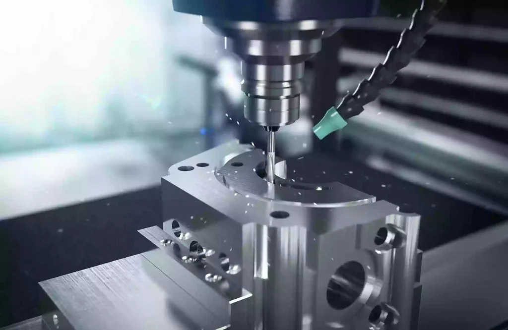
Causes and Solutions for Tool Buildup When Machining Aluminum on CNC Machining Centers
Tool buildup is a recurring machining issue we pay close attention to when producing aluminum components on CNC machining centers. During the machining of common aluminum alloys such as 6061 and 7075, aluminum chips can adhere to the cutting edges and flutes of milling tools, gradually forming built-up edges (BUE) or deposits of compacted aluminum.
This problem may not be immediately noticeable during the initial stages of machining. It often starts with a small amount of aluminum adhering to the cutting edge. As machining continues, the deposits accumulate and may eventually cover part of the cutting edge. Once this buildup begins to participate in the cutting process, the tool’s effective geometry changes, affecting surface finish, dimensional consistency, and tool life.
Based on our experience in aluminum CNC machining, tool buildup is not simply a matter of keeping cutting tools clean. It is often associated with several interacting factors, including cutting parameters, tool geometry, cooling and lubrication, and chip evacuation.
Common consequences include:
- Poor surface finish: Scratches, tearing, burrs, and rough surface areas may appear, particularly on finished surfaces and machined edges.
- Dimensional variations: Aluminum deposits change the effective cutting geometry, potentially causing dimensional deviations and profile inaccuracies.
- Accelerated tool wear: Accumulated chips increase cutting resistance and may lead to edge chipping, tool damage, or even workpiece damage.
- Reduced production efficiency: Frequent machine stops for tool cleaning, inspection, and parameter adjustments interrupt continuous production.
Aluminum alloys generally have good ductility and plasticity, which means they tend to produce continuous chips during cutting. When contact pressure and frictional heat increase while chips cannot escape efficiently, aluminum may adhere to the tool surface and gradually develop into a built-up edge.
For this reason, diagnosing tool buildup requires more than simply replacing the cutting tool. Material characteristics, tool condition, cutting parameters, cooling, and machine performance all need to be considered.
How Different Aluminum Alloys Affect Tool Buildup
Although alloys such as 6061 and 7075 are widely used in CNC machining, their chemical compositions, mechanical properties, and heat treatment conditions differ. These differences influence chip formation, cutting loads, and tool wear.
In our aluminum machining operations, we do not apply identical tooling and cutting parameters to every aluminum grade. Material designation, temper, and component geometry all influence the machining strategy.
6061 Aluminum
6061 offers a good balance of strength, machinability, and corrosion resistance, making it a common choice for structural and precision-machined components.
During cutting, 6061 can produce continuous chips. If the cutting edge is not sufficiently sharp or chip evacuation is restricted, aluminum may accumulate on the tool surface.
For thin-wall components, complex cavities, and precision profiles, particular attention should be paid to cutting loads and chip removal to prevent buildup from affecting surface finish and dimensional stability.
7075 Aluminum
7075 is generally stronger and harder than 6061, particularly in heat-treated conditions such as T6.
Its cutting behavior differs from that of 6061, so cutting loads, tool wear, and chip formation should be evaluated according to the actual material condition. Higher strength does not automatically mean a greater tendency to form built-up edges, and machining parameters developed for 6061 should not be transferred without verification.
Other Aluminum Alloys
Other aluminum families, including 2xxx and 5xxx series alloys, also require material-specific machining considerations. Some alloys with higher ductility may produce longer, more continuous chips, placing greater demands on cutting-edge quality and chip evacuation.
Before production, we confirm the material grade, temper, and drawing requirements, then select suitable tooling and cutting conditions based on the component geometry and machining operations.
Typical Conditions of Tool Buildup
In production, we normally assess tool buildup by inspecting the cutting edges and flutes, then comparing their condition with the chip formation and machined surface quality.
There are clear differences between normal cutting conditions and abnormal aluminum adhesion.
1. Normal Cutting: Clean Cutting Edges and Efficient Chip Evacuation
When cutting conditions are properly matched, the tool maintains a stable cutting process. The cutting edges shear the aluminum, and the resulting chips flow along the rake face into the flutes before being evacuated by the tool geometry, coolant, or compressed air.
Under these conditions, the cutting edges remain relatively clean, with no significant aluminum deposits, and the flutes are not obstructed by accumulated chips.
Typical characteristics include:
- Sharp cutting edges without noticeable aluminum adhesion.
- Continuous or segmented chips that leave the cutting zone without excessive accumulation.
- Stable cutting sounds without unusual vibration or friction.
- Consistent machined surfaces without significant tearing, scratches, or abnormal burrs.
- Dimensions that remain within the specified tolerances.
Continuous or curled chips are not necessarily a sign of abnormal machining. Their shape depends on the material condition, tool geometry, and cutting parameters. The more important considerations are whether chips can be evacuated efficiently and whether the cutting edges remain in good condition.
2. Abnormal Conditions: Built-Up Edges and Flute Blockage
When aluminum begins adhering to a cutting tool, two common conditions can occur.
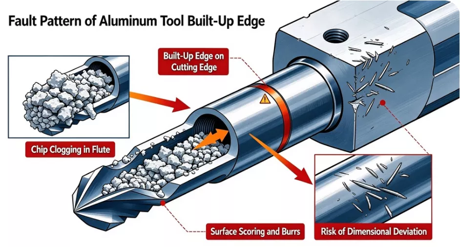
Built-Up Edge (BUE)
During cutting, high contact pressure and friction may cause aluminum to adhere to the rake face or cutting edge. As machining continues, more material accumulates and becomes compacted, forming a built-up edge.
This deposit changes the tool’s effective cutting geometry, affecting the actual cutting position and edge angle. In some cases, the built-up edge repeatedly forms and breaks away during machining, potentially tearing material from the workpiece surface and producing scratches, surface defects, and dimensional variations.
Aluminum Accumulation in the Flutes
Another common condition occurs when chips cannot leave the tool flutes efficiently and instead accumulate inside them.
Because aluminum chips are relatively ductile, they can deform and become entangled under cutting pressure and tool rotation. When the available flute space is insufficient, accumulated chips may obstruct the passage of newly generated material.
This is particularly important during deep-pocket milling, cavity machining, and operations involving substantial axial engagement. Once chip evacuation becomes restricted, the tool may recut previously generated chips, increasing cutting loads and localized heat. Severe cases can result in persistent tool buildup, abnormal wear, or edge breakage.
Tool Buildup Risks in Different CNC Machining Operations
Tool buildup does not occur exclusively in one type of aluminum machining operation. Different tool paths, engagement conditions, and chip evacuation directions create different risks during face milling, pocket milling, and finishing operations.
1. Face Milling
During face milling, a relatively large portion of the cutting tool engages with the workpiece surface, generating a concentrated volume of chips.
If spindle speed, feed rate, and radial engagement are not properly matched, localized cutting loads may become excessive, or chips may repeatedly pass through the machining area.
For large aluminum surfaces, we pay particular attention to insert edge condition, tool runout, and chip evacuation direction to prevent local buildup from affecting surface roughness and flatness.
2. Pocket and Cavity Milling
Pocket machining is particularly susceptible to chip evacuation problems.
The presence of sidewalls, bottom surfaces, and internal corners can cause chips to accumulate at the bottom or in restricted areas of the cavity. If the tool cannot remove these chips efficiently, subsequent passes may repeatedly engage with previously generated material.
Effective machining strategies should account for toolpath planning, step-down depth, and chip evacuation direction. Compressed air or directed coolant may also be used where appropriate.
3. Deep Slot and Deep Cavity Machining
Deep-slot machining presents two main challenges: increased tool overhang and restricted chip evacuation space.
As machining depth increases, chips may accumulate inside the slot, making it easier for the tool flutes to become blocked. If tool rigidity is also insufficient, vibration, sidewall damage, and dimensional deviations may occur.
Tool length-to-diameter ratio, flute length, cutting load, and chip evacuation methods should therefore be considered together.
4. Finishing Operations
Although finishing operations generally remove less material, they are more sensitive to cutting-edge condition and surface quality.
If chips remain on the workpiece after roughing, or if the finishing tool has already developed a small built-up edge, scratches and fine surface defects may appear on the final machined surface.
Before finishing, we inspect the workpiece surface, tool edges, and remaining machining allowance to prevent problems from earlier operations from carrying over into the final stage.
Main Causes of Tool Buildup in Aluminum CNC Machining
Tool buildup in aluminum machining is rarely caused by a single factor. In our production experience, several machining conditions often interact.
For example, a slightly worn cutting tool may not immediately cause serious problems. However, when combined with poor chip evacuation and insufficient lubrication, minor aluminum adhesion can quickly develop into more severe buildup.
The following five factors are among the main causes.
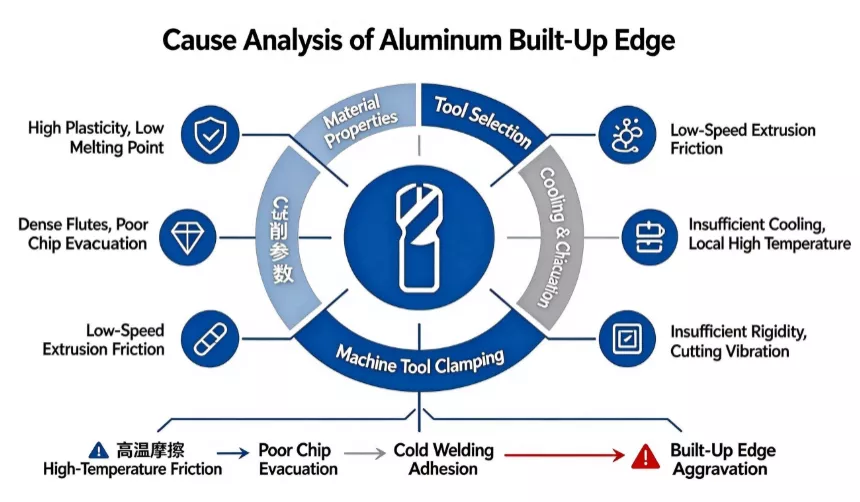
(1) Aluminum Alloy Properties: The Fundamental Contributing Factors
The material characteristics of aluminum alloys explain why their cutting behavior differs significantly from that of steel. Although aluminum is generally considered easy to machine, its ductility, plasticity, and relatively low melting temperature can contribute to chip adhesion.
1. High Ductility and Plasticity Promote Chip Adhesion
Aluminum alloys undergo plastic deformation during cutting and commonly produce continuous or relatively long chips. Unlike some brittle materials, aluminum chips do not always fracture naturally into small pieces. Instead, they may flow continuously along the tool’s rake face.
When contact pressure and friction between the tool and chips become excessive, aluminum can adhere to the tool surface. This is particularly likely when the cutting edge is not sufficiently sharp or the undeformed chip thickness is too small. Under these conditions, the tool may rub or compress the material instead of shearing it efficiently.
2. Low Melting Temperature and Localized Heat Accumulation
Pure aluminum has a melting point of approximately 660°C. However, the melting range of individual aluminum alloys varies with their chemical composition, so this value should not be treated as the exact melting point of every aluminum grade.
During high-speed cutting, friction and plastic deformation generate heat at the tool-workpiece and tool-chip interfaces. Although some of this heat is carried away by the chips, tool, and coolant, insufficient cooling or chip evacuation can allow localized heat to accumulate.
Higher temperatures can reduce the local deformation resistance of aluminum, making adhesion and material transfer more likely. Combined with high contact pressure, these conditions can promote the formation of built-up edges.
3. Soft Chips Can Become Entangled and Recirculated
Aluminum chips are generally lightweight and relatively ductile. During deep-pocket, narrow-slot, and complex cavity machining, they may remain in the cutting zone instead of being evacuated efficiently.
When the tool passes through the same area again, previously generated chips can re-enter the cutting path. This secondary cutting increases friction between the tool and chips and may scratch surfaces that have already been machined.
Therefore, effective chip evacuation depends not only on the available flute space but also on whether chips can actually leave the machining area.
(2) Tool Selection and Cutting Edge Condition: Key Factors Affecting Adhesion
Tool selection directly influences friction, chip formation, and evacuation efficiency during aluminum CNC machining. Even a capable CNC machining center can experience persistent tool buildup if the cutting geometry is unsuitable for aluminum.
1. Tool Type Does Not Match Aluminum Machining Requirements
Different materials require different tool surface characteristics and cutting-edge geometries.
For example, some coated milling tools designed for steel may not be suitable for aluminum machining. Depending on the coating characteristics, surface finish, and cutting conditions, these tools may create additional friction or encourage aluminum adhesion.
For general aluminum milling, we typically favor dedicated aluminum cutting tools with polished flutes, sharp cutting edges, and smooth rake faces. Uncoated carbide end mills are a common option. Specialized anti-adhesion coatings may also be suitable when supported by the tool manufacturer’s design and machining recommendations.
2. Excessive Flute Count Restricts Chip Space
The number of cutting edges directly affects the available flute space.
For tools of the same diameter, 4-flute or 6-flute end mills generally provide less space per flute than 2-flute or 3-flute designs. When densely spaced tools are used with substantial cutting depths or high feed rates, chips may not evacuate quickly enough.
For many aluminum milling applications, 2-flute and 3-flute end mills provide larger chip spaces and are often preferred. However, the appropriate flute count still depends on tool diameter, machining strategy, cutting depth, and surface finish requirements.
3. Unsuitable Helix Angle and Flute Geometry
The helix angle influences axial cutting forces, chip flow direction, and machining stability.
If the helix angle does not match the machining conditions, chips may not flow smoothly along the flutes. During deep-pocket or sidewall machining, it is also necessary to consider whether chips become trapped between the tool and workpiece.
When selecting aluminum milling tools, we therefore consider not only flute count and diameter but also helix angle, flute depth, surface finish, and overall tool rigidity.
4. Tool Wear and Cutting Edge Dulling
After extended use, cutting edges may develop wear, micro-chipping, or edge rounding.
A sharp cutting edge separates material with relatively low cutting resistance. A worn edge is more likely to rub and compress aluminum, increasing friction and the risk of adhesion. Even minor edge deterioration can affect surface quality during precision finishing.
When investigating surface tearing or roughness problems, we inspect the cutting edges for localized aluminum buildup, edge damage, and uneven wear rather than relying solely on accumulated machining time to determine whether a tool needs replacement.
5. Tool Surface Finish Affects Chip Flow
The condition of the rake face and flutes also influences chip movement.
Scratches, machining marks, or rough areas inside the flutes can obstruct chip flow and create locations where aluminum is more likely to adhere. As deposits accumulate, they can further restrict chip evacuation.
For aluminum machining, cutting tools should therefore combine sharp edges with smooth, well-polished flute surfaces.
(3) Improper Cutting Parameters: A Common Cause of Tool Buildup
Cutting parameters determine the actual engagement conditions between the tool and workpiece. They are among the most important variables to evaluate when troubleshooting aluminum machining problems.
Spindle speed, feed per tooth, axial depth of cut, and radial width of cut are interrelated. Increasing spindle speed or reducing feed rate alone does not necessarily resolve tool buildup. Adjustments should be based on tool specifications, machine capability, and the machining operation.
1. Mismatch Between Spindle Speed and Cutting Speed
Aluminum alloys generally support relatively high cutting speeds, and many aluminum-specific tools are designed to operate effectively at elevated speeds.
If spindle speed is too low, the tool may not reach a suitable cutting speed for the material and tool geometry. Under certain conditions, this can increase rubbing and compression instead of efficient material removal, contributing to tool adhesion.
However, higher spindle speed is not always better. Machine spindle limits, tool diameter, tool balance, overhang, and workholding rigidity must all be considered.
2. Incorrect Feed per Tooth
Excessive feed per tooth increases the load on each cutting edge, resulting in thicker chips and greater cutting resistance. If flute capacity and chip evacuation cannot accommodate the increased chip volume, accumulation and compaction may occur.
An excessively low feed per tooth can also create problems. When the feed is insufficient, particularly with a slightly worn cutting edge or minimal machining allowance, the tool may rub against the workpiece rather than produce effective chips. This can increase the likelihood of built-up edge formation.
Feed adjustments should therefore be based on feed per tooth rather than programmed feed rate alone.
3. Unsuitable Axial Depth and Radial Width of Cut
Axial depth and radial width determine the portion of the tool engaged in cutting and directly influence machining loads.
Excessive engagement increases cutting resistance and chip volume. If the available flute space cannot accommodate the generated chips, blockage may occur.
For deep cavities, narrow slots, and complex profiles, machining allowance should be removed in appropriate stages based on tool diameter, effective flute length, and available machining space.
On the other hand, an excessively small engagement combined with insufficient feed may cause rubbing and ploughing. Cutting parameters should therefore be adjusted as a coordinated set rather than by simply reducing depth of cut.
4. Poor Tool Entry, Exit, and Toolpath Planning
Tool movement also affects cutting stability.
An unsuitable entry path may create excessive instantaneous cutting loads when the tool first engages the workpiece. Similarly, abrupt changes in feed rate around corners or narrow sections can cause localized overloading.
Long dwell periods near the workpiece, repeated passes through accumulated chips, or unnecessary tool rotation without effective cutting can also increase the risk of aluminum adhesion.
For complex cavities and continuous profiles, toolpath planning should account for entry and exit strategies, local load variations, and chip evacuation.
(4) Cooling, Lubrication, and Chip Evacuation Problems
Aluminum machining requires more than temperature control. The interaction between the tool, workpiece, and chips must also be managed to maintain stable cutting conditions.
Cooling, lubrication, and chip evacuation are closely related and should be evaluated together.
1. Inadequate Cutting Fluid Lubricity
Cutting fluid does more than remove heat. It also helps reduce friction between the tool, workpiece, and chips while supporting smoother chip flow.
If the fluid does not provide sufficient lubrication, adhesion and friction between the cutting tool and aluminum may increase, promoting built-up edge formation.
For wet aluminum machining, cutting fluid should be selected according to the material and machining process. Its lubricating properties, aluminum compatibility, and concentration should be monitored throughout production.
2. Insufficient Coolant Flow or Incorrect Nozzle Position
Even when the correct cutting fluid is selected, it cannot perform effectively if it does not reach the actual cutting zone.
During deep-hole, deep-cavity, and enclosed-pocket machining, limited access may prevent coolant from reaching the tool-workpiece interface. Accumulated chips can further obstruct coolant flow.
Simply increasing the total coolant volume may not solve the problem. Nozzle position, spray direction, and delivery pressure should also be adjusted to ensure effective coverage and chip removal.
3. Inadequate Air Blast and Chip Removal
When compressed air is used for chip evacuation, airflow direction, pressure, and nozzle placement all influence the result.
If the airflow cannot remove chips from around the tool, aluminum may remain in the machining area and re-enter the cutting path as the tool moves.
This is particularly important during pocket milling, sidewall machining, and deep-slot operations. The airflow should guide chips out of the machining area rather than simply circulate them within the cavity.
For dry machining, compressed-air capacity and thermal management should be evaluated carefully. For wet machining, coolant delivery and chip evacuation must both remain effective.
(5) Machine Performance and Workholding: Often Overlooked Factors
In some production situations, tool buildup continues even after the cutting tool has been replaced and machining parameters adjusted. In these cases, machine condition, tool installation, and workholding should also be investigated.
1. Insufficient Machine Rigidity or Unstable Spindle Operation
Although aluminum is relatively easy to cut, high-speed and continuous machining still require adequate dynamic rigidity.
Excessive spindle runout or vibration within certain speed ranges can change the contact conditions between the tool and workpiece, causing uneven loads on the cutting edges.
This instability may produce surface chatter, localized overcutting, and abnormal tool wear while increasing the possibility of aluminum adhesion.
2. Insufficient Workpiece Clamping
Workholding directly affects machining stability.
If clamping force is insufficient or support positions are poorly arranged, cutting forces may cause slight workpiece movement or elastic deformation. This is particularly important when machining thin-wall aluminum parts and large structural components.
Any movement can change the actual cutting load, resulting in unstable cutting conditions, reduced surface quality, and dimensional deviations.
Before machining, the fixture layout and support positions should be selected according to the workpiece geometry, wall thickness, and cutting-force direction. Additional support may be required to minimize deformation and vibration.
3. Excessive Tool Overhang
Tool overhang affects the rigidity of the entire cutting system. Longer overhang generally reduces resistance to cutting forces and increases the possibility of bending and vibration.
This is particularly relevant during deep-cavity machining. Using an excessively long tool without adjusting the cutting parameters or tool geometry may lead to noticeable vibration.
Where machining depth permits, tool overhang should be minimized. Tool diameter, flute length, and clamping method should also be selected according to the available machining space.
Effects of Tool Buildup on Machining Quality and Production Efficiency
Tool buildup affects more than the appearance of a cutting tool. Once built-up edges continue to form, the actual cutting conditions gradually deviate from the intended machining setup, affecting part quality, process stability, and production costs.
1. Deterioration of Workpiece Surface Finish
When aluminum adheres to the cutting edge, portions of the built-up material may break away during machining and leave irregular scratches or torn areas on the workpiece.
For cosmetic surfaces, sealing interfaces, and components with specified surface roughness requirements, these defects may prevent the part from meeting drawing specifications.
In addition, secondary cutting caused by poor chip evacuation can leave scratches on previously machined surfaces.
2. Dimensional and Geometric Accuracy Variations
Once aluminum deposits form on a cutting edge, they may participate in the cutting process and change the effective tool dimensions.
For example, during side milling and profile machining, adhered material can alter the effective cutting radius, causing the finished dimensions to deviate from the programmed values.
If built-up edges repeatedly form and break away, dimensional errors may become inconsistent, making it more difficult to maintain accuracy across production batches.
3. Accelerated Tool Wear and Unexpected Tool Damage
Adhered aluminum increases friction between the tool and chips and may obstruct normal chip evacuation. As cutting loads continue to rise, the cutting edge becomes more susceptible to abnormal wear, micro-chipping, and localized damage.
If chip blockage is not addressed promptly, severe cases may result in tool breakage and damage to the workpiece surface.
4. Longer Cycle Times and Reduced Production Efficiency
During batch production, frequent tool cleaning, edge inspection, and parameter adjustments increase non-cutting time.
Recurring tool buildup may also require additional first-piece inspections to confirm that dimensional accuracy and surface quality have returned to acceptable levels.
These interruptions reduce machine utilization and increase tooling costs, rework, and scrap risks. Establishing consistent tool management and in-process inspection procedures is therefore more effective than repeatedly reacting to problems after they occur.
How to Identify the Source of Tool Buildup During Production
When tool buildup is detected, immediately replacing the tool or changing cutting parameters without identifying the underlying cause may provide only temporary improvement.
Based on our production troubleshooting experience, we assess the tool, chip condition, workpiece surface, and machine operating behavior together.
1. Inspect the Cutting Edges and Flutes
First, determine where the aluminum is accumulating.
If deposits are concentrated around the tool tip and primary cutting edges, inspect edge sharpness, tool surface condition, and cutting loads.
If aluminum is mainly accumulating inside the spiral flutes, focus on available chip space, evacuation direction, and whether coolant or compressed air can effectively remove the chips.
2. Examine Chip Formation
Chip characteristics provide useful information about cutting conditions.
Long, continuous chips that easily become entangled indicate that chip control and evacuation should be evaluated.
Compacted chips, repeated chip recutting, or visible aluminum adhesion suggest that chip removal may be restricted or that secondary cutting is occurring.
Chip color and shape should not be used alone to determine cutting temperature or the exact cause of buildup. They should be considered alongside other machining observations.
3. Check Workpiece Surface Defects
Different surface defects can indicate different machining problems.
- Localized scratches or tearing: Inspect for built-up edges and chips re-entering the cutting zone.
- Abnormal surface roughness: Check edge wear, tool runout, and cutting parameters.
- Profile or dimensional variations: Examine effective tool size, aluminum buildup, and machine operating conditions.
- Increased burr formation: Inspect cutting-edge sharpness, machining direction, and feed conditions.
4. Evaluate Machine Operating Conditions
If tool buildup occurs together with unusual cutting sounds, vibration, or changes in spindle load, tool overhang, workholding rigidity, and spindle condition should be investigated.
For continuous production, comparing spindle-load behavior between normal and abnormal machining cycles can also help determine whether increased cutting resistance is contributing to the problem.
This systematic approach helps turn tool buildup from a general surface defect into a more clearly defined process issue, making subsequent adjustments more targeted.
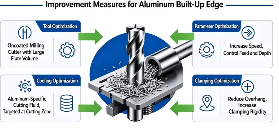
Practical Solutions for Reducing Tool Buildup in Aluminum Machining
When addressing different types of tool buildup, we do not rely on a single parameter adjustment to determine whether the problem has been resolved. Instead, we evaluate tool condition, chip formation, toolpaths, and cooling and evacuation conditions together.
The following measures are practical starting points for improving aluminum machining stability.
1. Optimize Tool Selection and Tool Condition
First, confirm that the cutting tool is suitable for the aluminum alloy and machining operation.
For general aluminum milling, consider dedicated aluminum end mills with sharp cutting edges, polished flutes, and sufficient chip space. Select 2-flute or 3-flute designs according to tool diameter and machining requirements, avoiding densely fluted tools when chip evacuation space is insufficient.
For finishing operations, cutting-edge integrity and surface condition require particular attention. If deposits, wear, or micro-chipping are detected, the tool should be cleaned, inspected, or replaced before the next machining stage.
Tool clamping and radial runout should also be checked to reduce uneven loading across the cutting edges.
2. Adjust Cutting Parameters According to Tool Specifications
Cutting parameters should be established using the tool manufacturer’s recommendations and verified against actual machine performance and workpiece geometry.
The following factors should be considered:
- Select an appropriate cutting speed based on tool diameter and material characteristics, avoiding excessively low spindle speeds or speeds beyond stable machine operation.
- Set a suitable feed per tooth to ensure effective chip formation without excessive cutting loads.
- Use staged material removal for deep cavities, slots, and areas with substantial machining allowance.
- Adjust feed rates according to profile changes to prevent localized overloading around corners and narrow sections.
- Optimize entry, exit, and rapid movement paths to reduce unnecessary recutting and chip accumulation.
When tool buildup has already occurred, inspect actual chip thickness and tool load before making targeted adjustments rather than reducing all parameters indiscriminately.
3. Improve Cooling, Lubrication, and Chip Evacuation
Cooling, lubrication, and chip removal should be optimized as an integrated process.
For wet machining, select a cutting fluid suitable for aluminum alloys and maintain its concentration and condition according to the manufacturer’s recommendations. Check nozzle direction, delivery pressure, and flow rate to ensure coolant reaches the actual cutting zone.
For deep cavities and enclosed areas, particular attention should be paid to whether chips can leave the machining space efficiently. If conventional coolant delivery is insufficient, directed coolant or additional chip evacuation methods may be considered according to machine capability.
For dry or air-assisted machining, inspect compressed-air pressure, flow rate, and nozzle direction to prevent chips from circulating repeatedly within the cutting area.
4. Improve Workholding and Machining Strategies
If tool selection and cutting parameters are already appropriate but buildup, chatter marks, or dimensional variations persist, machine stability and workholding should be investigated.
Before machining, verify fixture positioning and clamping conditions. Thin-wall components, long workpieces, and large aluminum structures may require carefully positioned supports based on cutting-force direction to prevent movement or deformation.
Tool overhang should be minimized wherever possible, and tool geometry should match the required machining depth. For deep-cavity operations, optimizing machining sequence, staged material removal, and toolpaths can help reduce vibration and chip evacuation difficulties.
Tool Management and Quality Monitoring in Batch Production
For a single machined component, occasional tool buildup may only require cleaning or a parameter adjustment. In batch production, however, the same issue can repeatedly occur if there is no consistent tool inspection and process monitoring system.
In addition to optimizing cutting tools and parameters, tool condition management should be incorporated into routine production control.
1. Maintain Tool Usage and Replacement Records
Different tools experience different cutting loads depending on the material and machining operation. A single replacement interval should not be applied to every tool.
Production records can include tool model, workpiece material, accumulated cutting time, number of machined parts, and observed wear conditions. Comparing tool performance across production batches helps establish appropriate inspection and replacement intervals for individual operations.
2. Strengthen First-Piece Inspection
Before batch production begins, the first machined part should receive particular attention.
In addition to checking critical dimensions and geometric tolerances, inspect the surface for scratches, burrs, and abnormal machining marks. The cutting edges and chip evacuation conditions should also be evaluated.
If noticeable tool buildup is already present during first-piece machining, the process should be adjusted before continuous production begins. This prevents unstable cutting conditions from being repeated throughout the batch.
3. Monitor Critical Machining Operations
For deep cavities, thin-wall components, complex profiles, and parts with demanding surface finish requirements, more frequent in-process inspections may be appropriate.
Key inspection points include tool deposits, flute blockage, unusual cutting sounds, and changes in critical workpiece dimensions.
4. Use Inspection Results to Improve the Machining Process
Tool condition and dimensional accuracy are closely related.
When inspection results show that dimensions are gradually shifting away from the target, tool wear, aluminum buildup, and machine condition should be investigated. Simply changing tool offsets without identifying the underlying cause may conceal a developing process problem.
For batch production, maintaining records of critical dimensions, tool usage, and machining abnormalities helps establish more consistent manufacturing conditions.
Conclusion
Tool buildup during aluminum CNC machining may appear to be a simple case of aluminum adhering to cutting edges or flutes. In practice, it reflects an imbalance between cutting conditions, chip evacuation, and cooling and lubrication.
The plasticity and ductility of aluminum alloys make their chips more susceptible to deformation and adhesion. Meanwhile, dull cutting edges, insufficient flute space, unsuitable cutting parameters, and inadequate cooling and lubrication can further aggravate the problem.
Based on our experience in aluminum CNC machining, resolving tool buildup requires more than replacing the cutting tool or simply increasing spindle speed. The first step is to identify whether aluminum is forming built-up edges around the cutting edges or accumulating inside the flutes and workpiece cavities. Tooling, cutting parameters, and machining paths can then be adjusted according to the actual cause.
For batch production, consistent machining quality depends on effective process planning and continuous production control. Proper aluminum tool selection, coordinated cutting parameters, efficient cooling and chip evacuation, and stable machine and workholding conditions all help reduce surface defects, dimensional variations, and unexpected downtime.
At Xtmade, we specialize in custom aluminum CNC machining, supported by an engineering team with more than 20 years of industry experience. For different aluminum alloys, component geometries, and precision requirements, we evaluate customer-provided drawings, CAD files, and technical specifications to determine suitable machining processes, tooling, cutting strategies, and quality control requirements.
From initial DFM reviews to production and dimensional inspection, our focus is on matching each machining operation to the component’s geometry and technical requirements to maintain dimensional consistency and surface quality throughout production.
If you have aluminum components requiring CNC machining, send our engineering team your drawings or CAD files for a review of material selection, manufacturing processes, and production feasibility.