Robot Joint Modules: Components, Manufacturing Processes, and Precision Requirements
At the 2026 APEC Economic Leaders’ Meeting in Shenzhen, humanoid robots attracted considerable attention. At the event’s media center, robots demonstrated practical tasks such as preparing coffee, serving ice cream, and delivering refreshments to visitors and journalists. These demonstrations offered a glimpse of how robotics is moving beyond controlled demonstrations and into real-world applications.
Behind every movement of a humanoid robot, from walking and turning to raising an arm or grasping an object, is a coordinated system of robotic joints. These joints allow different sections of the robot to move independently while maintaining balance, positioning, and controlled force.
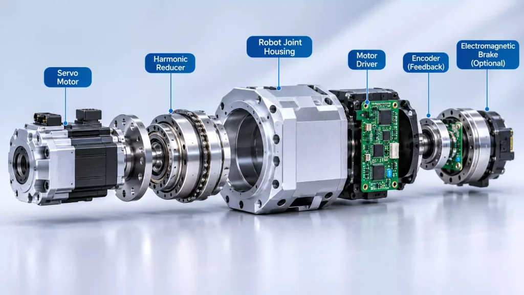
A robot joint is much more than a motor that rotates. A typical robot joint module integrates several functional components, including a servo motor, reducer, encoder, and motor driver. Some designs also incorporate an electromagnetic brake. These components are supported by mechanical structures such as housings, output shafts, bearing seats, and mounting flanges.
The performance of a robot joint depends not only on its motor and transmission system but also on the dimensional accuracy and assembly quality of its mechanical components. Bearing bores, shaft alignment, mounting surfaces, and connection features all influence how the assembled joint operates.
This article examines the main components of robot joint modules, the mechanical parts used in their construction, common manufacturing processes, and the precision requirements involved in producing reliable robotic joint components.
What Are the Main Components of a Robot Joint Module?
A robot joint module is an integrated electromechanical assembly designed to provide controlled rotational movement. Although its configuration varies depending on the robot’s application, most designs combine power generation, speed reduction, motion feedback, and control functions in a compact structure.
Servo Motor: The Power Source of the Joint
The servo motor converts electrical energy into mechanical rotation and provides the initial driving force for a robot joint.
Unlike conventional motors used for simple continuous rotation, robotic servo motors require accurate position control, responsive acceleration and deceleration, and consistent torque output.
One common design challenge is balancing motor speed, torque, and overall size. High-speed motors can provide substantial power in a relatively compact package, but their direct output may not deliver sufficient torque for many robotic applications. Using a larger, low-speed motor can increase the overall weight and dimensions of the joint.
For this reason, many robot joint designs combine a high-speed servo motor with a reducer to achieve the required output speed and torque.
The motor’s mounting arrangement is also important. Its positioning features, mounting holes, and connection surfaces must match the joint housing to ensure accurate installation and proper alignment.
Reducer: Controlling Speed and Increasing Torque
The reducer is a key transmission component in a robot joint. It reduces the motor’s rotational speed while increasing the available output torque.
Common reducer types used in robotics include:
- Harmonic reducers: Compact designs with high reduction ratios and low backlash, commonly used in collaborative robots, lightweight robotic arms, and humanoid robot joints.
- RV reducers: Known for their rigidity, load capacity, and resistance to impact, making them suitable for industrial robot joints carrying heavier loads.
- Planetary reducers: Offer compact transmission structures and good efficiency, with applications across different robotic drive systems.
Each reducer type has different characteristics in terms of backlash, stiffness, transmission efficiency, torque capacity, and precision. Selection depends on the joint’s load, speed, movement requirements, and available installation space.
From a manufacturing perspective, the reducer must also fit accurately within the surrounding mechanical structure. Mounting dimensions, locating features, connection holes, and contact surfaces all contribute to proper assembly.
Motor Driver: Controlling Motor Operation
The motor driver converts control commands from the robot’s control system into electrical signals that operate the servo motor.
It commonly manages current, speed, and position control loops, while also providing functions such as overcurrent protection, temperature monitoring, and fault detection.
Not every robot joint contains its own driver. Some designs integrate the driver electronics directly into the joint module, while others locate them in an external control cabinet or a separate electronic assembly.
This design choice affects the internal layout, electrical connections, thermal management, and available installation space.
Encoder: Providing Position Feedback
An encoder measures rotational position and provides feedback to the motor control system.
Two common configurations are used in robot joint modules:
- Motor-side encoder: Measures the position of the motor rotor and provides feedback for motor commutation and servo control.
- Output-side encoder: Measures the position of the reducer’s output shaft, providing information about the actual movement of the joint.
Why do some high-performance robot joints use two encoders?
The motor and output shaft are connected through a reducer, which may introduce elastic deformation, transmission errors, and small amounts of backlash. Therefore, calculating output position solely from motor-side feedback may not fully represent the actual position under load.
Using both motor-side and output-side feedback can help improve position control and compensate for certain transmission-related errors.
Electromagnetic Brake: Holding the Joint Position
An electromagnetic brake is used to hold a joint in position when the motor is not actively driving it.
This is particularly important for vertical robot axes and joints that support gravitational loads. If power is interrupted, the brake can help prevent the joint from rotating unintentionally under the weight of the attached structure.
However, not every robot joint requires a brake. Its inclusion depends on the joint’s load, mounting orientation, safety requirements, and overall mechanical design.
For lightweight robotic systems, the brake’s dimensions and weight must also be considered when designing the integrated joint structure.
What Mechanical Parts Make Up a Robot Joint Module?
The motor, reducer, driver, and encoder provide the main power transmission and control functions. However, these components cannot operate as a complete joint without a supporting mechanical structure.
A robot joint module also contains precision mechanical parts that hold, locate, connect, and support its functional components.
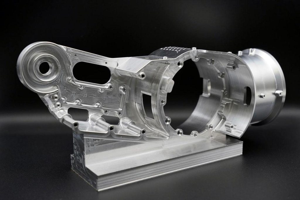
Robot Joint Housing
The robot joint housing is one of the main structural components. It provides installation space and mechanical support for the motor, reducer, bearings, and other internal assemblies.
Depending on the joint design, the housing may have a cylindrical, tubular, rectangular, or multi-cavity structure.
Typical manufacturing requirements include:
- Accurate dimensions for motor and reducer mounting cavities.
- Precise bearing bores and their relative positions.
- Flatness and perpendicularity of mounting surfaces.
- Accurate locations for threaded holes, locating holes, and connection features.
- Consistent wall thickness and sufficient structural rigidity.
Aluminum alloys are commonly used for robot joint housings because of their relatively low weight, good machinability, and thermal conductivity.
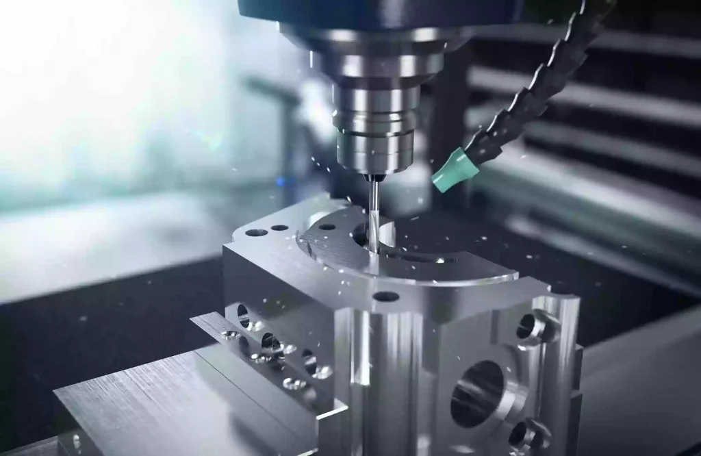
However, thin-wall housings and complex multi-cavity structures can deform during CNC machining. Clamping forces, cutting forces, and residual material stress may all affect the final dimensions.
Proper workholding, machining sequence planning, and cutting parameter selection are therefore important when producing these components.
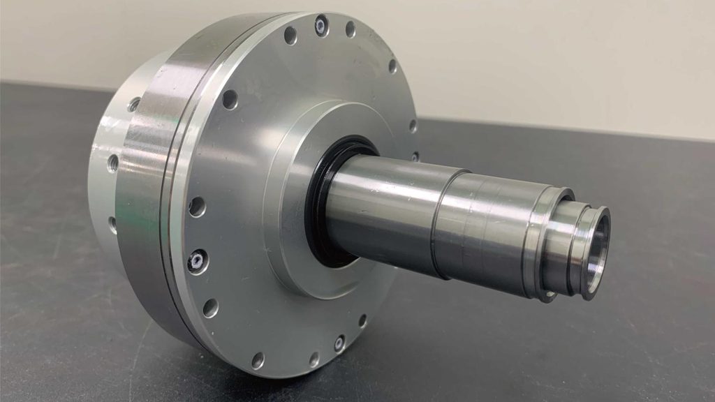
Output Shafts and Flanges
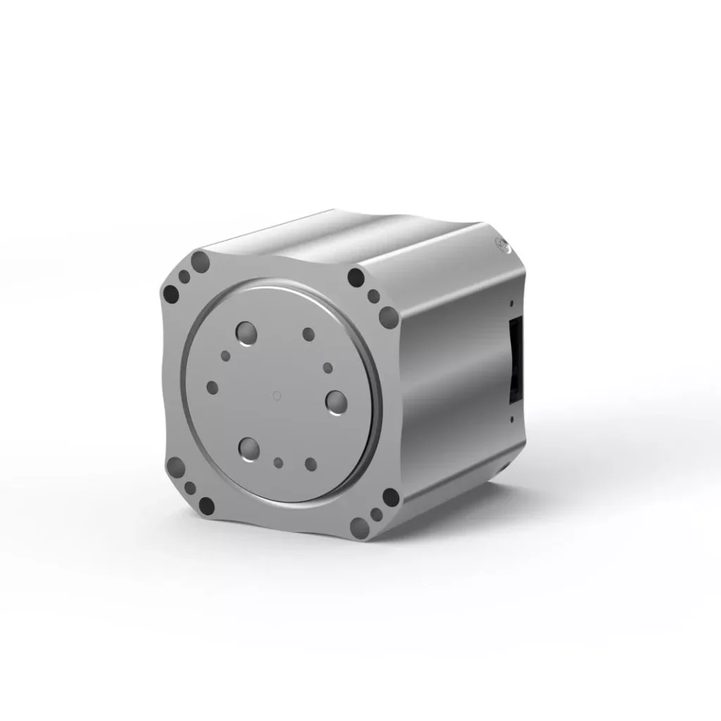
The output shaft transfers torque from the reducer to the external mechanical structure, while the output flange provides a connection interface for robot links and other moving components.
These parts may contain multiple stepped diameters, shoulders, bearing seats, threaded holes, and locating features.
Important manufacturing considerations include:
- Concentricity between different shaft sections.
- Dimensional accuracy of bearing mounting surfaces.
- Flatness and perpendicularity of flange faces.
- Positional accuracy of locating and threaded holes.
- Runout of shaft ends and flange connection surfaces.
The dimensional relationship between the output shaft, bearings, and reducer must be considered during machining. Meeting an individual diameter tolerance does not necessarily mean the complete shaft will meet its assembly requirements.
Bearing Seats and Mounting Components
Bearing seats and mounting components support rotating elements and maintain the relative positions of shafts, reducers, and other mechanical assemblies.
These parts commonly contain precision bores, locating shoulders, and mounting features.
Bearing bore accuracy is particularly important. An oversized or undersized bore can affect the fit between the bearing and its housing. Deviations in roundness or position may also influence assembly accuracy and bearing operation.
For structures containing multiple bearing locations, the alignment and relative positions of the bores must also meet the specified design requirements.
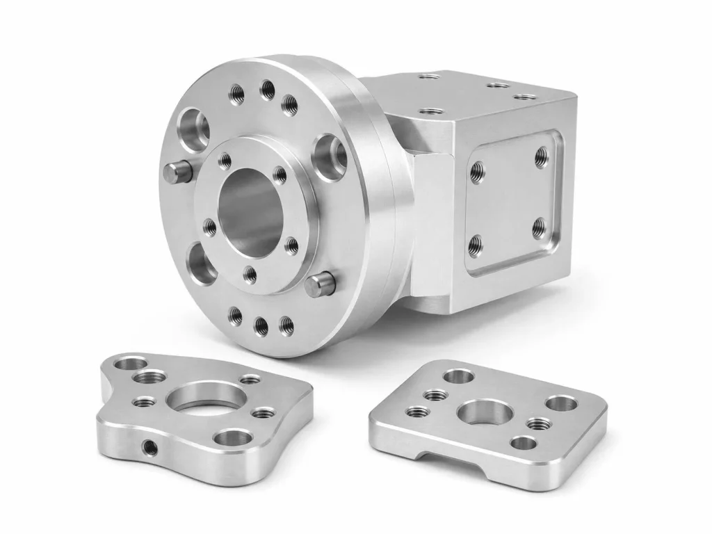
Motor End Covers and Connection Plates
Motor end covers and connection plates are used to secure motors, connect different housing sections, and provide assembly reference surfaces.
Typical features include motor locating shoulders, mounting holes, threaded holes, and stepped connection surfaces.
Although these parts may appear relatively simple, their locating dimensions and hole positions affect how accurately the motor aligns with the surrounding housing.
In compact robot joint modules, several mechanical components must fit together within limited installation space. Dimensional deviations in individual parts can accumulate and affect the final assembly.
Manufacturing Processes Used for Robot Joint Components
Robot joint components have different geometries, materials, and dimensional requirements. Their manufacturing processes must therefore be selected according to part structure, tolerances, surface requirements, and production quantities.
CNC milling, CNC turning, drilling, tapping, and surface finishing are among the common processes used to manufacture precision robotic joint components.
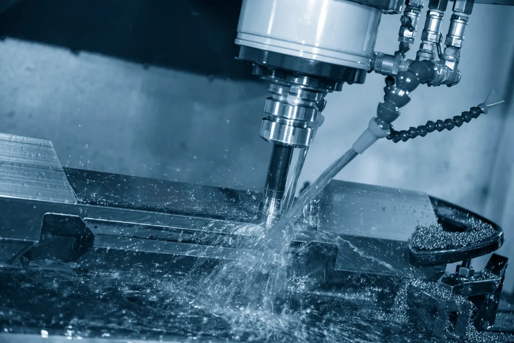
CNC Milling for Complex Joint Housings
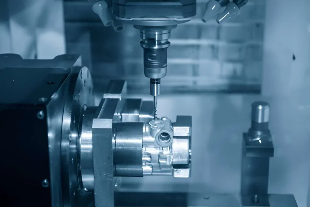
CNC milling is widely used to manufacture robot joint housings with complex external profiles, internal cavities, stepped surfaces, and multi-directional holes.
For example, an aluminum joint housing may require machining of a motor cavity, reducer mounting face, bearing seat, and multiple threaded holes. These features are distributed across different surfaces and require careful control of machining references and operation sequences.
Depending on the part geometry, three-axis, four-axis, or five-axis CNC machining may be selected.
Multi-axis machining can reduce repeated repositioning and help maintain positional relationships between different features. However, the appropriate machining strategy still depends on tool accessibility, workholding conditions, part geometry, and tolerance requirements.
CNC Turning for Output Shafts and Cylindrical Components
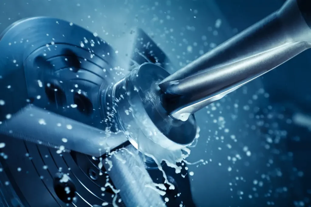
CNC turning is commonly used to manufacture output shafts, sleeves, locating rings, and other rotational components.
Typical machining features include:
- External diameters and internal bores.
- Stepped sections and shoulders.
- End faces and chamfers.
- Grooves and threads.
- Bearing fitting surfaces.
For robot joint output shafts, controlling diameter and length is only part of the requirement. Concentricity between shaft sections, roundness, and surface finish are also important.
For components that combine turning and milling features, an appropriate machining strategy can reduce repeated setups and help maintain dimensional relationships.
Drilling, Tapping, and Precision Hole Machining
Robot joint components often contain numerous mounting holes, locating holes, and threaded holes.
These features secure the motor, reducer, bearing seats, and external connection structures. Manufacturing requirements include not only hole diameter and thread dimensions but also hole spacing, depth, positional accuracy, and perpendicularity.
For precision features such as bearing bores and locating holes, additional operations such as boring, reaming, or other finishing processes may be required.
For housings with holes distributed across multiple surfaces, machining references and operation sequences must be carefully planned to maintain their relative positions.
Surface Finishing and Secondary Operations
Robot joint components also require surface protection and finishing according to their functional and environmental requirements.
Common finishing processes include:
- Anodizing: Frequently used for aluminum housings and mounting components to improve corrosion resistance and provide different surface appearances.
- Sandblasting: Creates a consistent surface texture and improves visual appearance.
- Passivation: Used on certain stainless steel components to improve corrosion resistance.
- Precision grinding: Applied to surfaces requiring tighter dimensional control and improved surface quality.
- Deburring: Removes sharp edges and machining burrs that could interfere with assembly or operation.
Surface finishing must be considered as part of the dimensional manufacturing process. For example, anodizing changes the surface dimensions of aluminum components. The coating thickness and final fitting dimensions should therefore be considered before machining is completed.
For precision bearing bores, locating shoulders, and other mating surfaces, masking or additional finishing may be necessary depending on the drawing requirements.
Critical Precision Requirements for Robot Joint Components
Robot joint components often contain multiple machining features that must meet dimensional and geometric requirements simultaneously. A part can meet an individual size tolerance while still failing to satisfy its overall geometric or assembly requirements.
Several precision factors are particularly important.
Dimensional Tolerances and Fit Requirements
Bearing bores, output shafts, motor mounting cavities, and reducer locating features require dimensional tolerances based on their intended functions.
Examples include:
- The fit between a bearing’s inner ring and the shaft.
- The fit between a bearing’s outer ring and the housing bore.
- Reducer locating dimensions and mounting interfaces.
- Connection dimensions between the motor and mounting plate.
These fits must be determined according to bearing type, load, rotational speed, and assembly method. Applying the same tolerance to every mounting feature is rarely appropriate.
Concentricity, Perpendicularity, and Position Accuracy
Many robot joint components contain features that must maintain specific geometric relationships.
For example, multiple shaft sections may need to remain concentric. Bearing bores must maintain their specified positions relative to other locating features. Output flange faces may also require controlled perpendicularity and runout.
These geometric characteristics affect component alignment and can influence the operating condition of rotating assemblies.
Establishing appropriate machining datums is therefore essential. When multiple critical features can be machined from consistent reference surfaces, their relative positions are generally easier to control.
Surface Finish and Contact Surface Quality
Different areas of a robot joint component require different surface finish levels.
A non-functional external surface does not necessarily require the same roughness as a bearing fitting surface, sealing surface, or precision locating face.
Excessive surface roughness on a mating surface may affect contact conditions and assembly quality. Other functional areas may have specific surface requirements related to friction, sealing, or wear.
Surface finish specifications should therefore be assigned according to the function of each area rather than applying the same requirement across the entire component.
Lightweight Design and Structural Rigidity
Lightweight construction is an important consideration in collaborative robots and humanoid robots.
Aluminum alloy housings can reduce joint weight, but thin-wall structures are more susceptible to deformation caused by cutting forces, clamping forces, and residual stress.
Manufacturing considerations include:
- Wall thickness distribution and structural rigidity.
- Workholding positions and clamping force.
- Roughing and finishing sequences.
- Cutting parameters and machining allowance.
- Stress relief and dimensional reinspection when necessary.
Lightweight design does not simply mean reducing wall thickness. It requires balancing weight, strength, rigidity, and manufacturing feasibility.
Common Manufacturing Challenges in Robot Joint Components
Understanding the required tolerances is only one part of precision manufacturing. The next challenge is achieving these requirements consistently during actual production.
Robot joint components often combine complex geometries, multiple precision features, and demanding assembly relationships. Several manufacturing challenges deserve particular attention.
Thin-Wall Housing Deformation During CNC Machining
Thin-wall aluminum housings are a typical example of precision machining challenges in robotics.
Because their walls have limited rigidity, they can deform under clamping and cutting forces. A housing may maintain its shape while clamped but spring back after the fixture is released, resulting in dimensional deviations.
Several manufacturing measures can help reduce this risk:
- Use suitable workholding methods to avoid concentrated clamping forces.
- Plan roughing and finishing operations according to the part structure.
- Control cutting depth and feed parameters.
- Reinspect critical dimensions after unclamping.
- Use staged machining when necessary to reduce deformation.
Maintaining Positional Accuracy Across Multiple Precision Holes
Robot joint housings often contain motor mounting holes, reducer locating bores, and bearing seats.
These features are not independent. They must maintain specific positional, angular, and alignment relationships.
Frequent changes in workholding references may introduce accumulated positioning errors, affecting the relationship between different holes.
A suitable machining datum system should therefore be established before production, followed by an operation sequence that maintains the required positional relationships.
Achieving Consistent Fits Between Mating Components
A robot joint module may contain several separately manufactured mechanical components, including housings, output shafts, bearing seats, and connection flanges.
Even when each component meets its individual dimensional tolerance, an unsuitable tolerance combination can still cause assembly problems.
Examples include excessively tight fits, positioning deviations, and inconsistent connections.
Manufacturing should therefore consider not only individual part dimensions but also the functional relationships between mating components.
Critical fitting dimensions should be evaluated against the engineering drawing, tolerance scheme, and assembly requirements.
Controlling Dimensional Changes After Surface Treatment
Anodizing, plating, and other surface finishing processes can change the final dimensions of a component.
For non-functional external surfaces, these changes may have little effect. However, dimensional changes on bearing bores, locating shoulders, and precision mounting features can affect final assembly.
Surface treatment requirements should be identified before machining. Functional fitting areas may need masking or additional finishing, while suitable machining allowances should be established for coated surfaces.
Quality Inspection for Precision Robot Joint Components
Quality inspection involves more than checking whether individual dimensions fall within tolerance. It must also verify critical geometric characteristics, surface quality, and assembly-related dimensions.
Dimensional Inspection
Common inspection instruments include:
- Calipers and micrometers for external dimensions and general measurements.
- Bore gauges for bearing bores and other internal diameters.
- Height gauges for stepped dimensions and vertical measurements.
- Precision gauges for specific hole sizes and fitting dimensions.
Critical dimensions such as bearing bores and output shaft fitting surfaces should be inspected using instruments appropriate for their tolerance requirements.
Geometric Tolerance Inspection
For complex robot joint components, conventional measuring tools may not be sufficient to verify all geometric relationships.
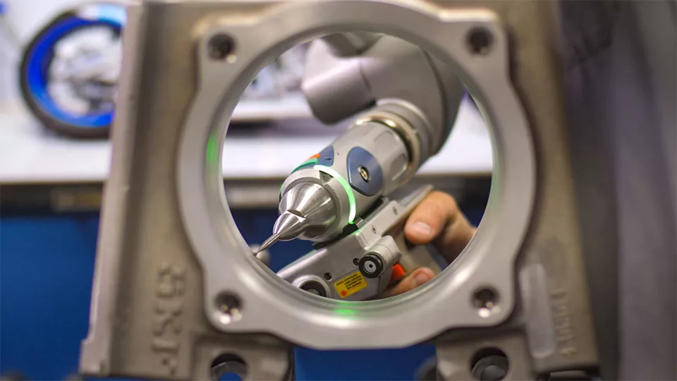
A coordinate measuring machine (CMM) can inspect multiple features and their spatial relationships, including:
- Hole position.
- Flatness and perpendicularity.
- Concentricity and related geometric characteristics.
- Complex profiles and dimensional features.
For housings with multiple mounting references and complex hole patterns, CMM inspection provides more comprehensive dimensional data.
Surface Quality and Quality Documentation
Depending on the engineering drawing, additional inspection may include surface roughness measurement, burr inspection, visual checks, and identification of scratches or other surface defects.
For projects requiring formal quality documentation, manufacturers may also provide:
- First Article Inspection (FAI) reports.
- Dimensional inspection reports.
- Material Test Reports (MTR).
- Relevant surface treatment records.
These inspection records and material traceability documents help customers verify whether the supplied components meet their technical requirements.
How to Choose a Manufacturing Partner for Robot Joint Components
Robot joint components often involve complex geometries, multiple precision features, and demanding assembly requirements. Choosing a manufacturing partner should therefore involve more than comparing machine counts or quotations.
Several capabilities are worth evaluating.
Complex Part Machining Capability
Robot joint housings often contain multi-sided features, internal cavities, and precision holes. A manufacturer should have suitable CNC milling, turning, and multi-axis machining capabilities and be able to select processes according to the part geometry.
Understanding of GD&T and Assembly Requirements
For bearing seats, output shafts, and connection flanges, the manufacturer should understand dimensional tolerances, geometric tolerances, and fitting requirements rather than treating every dimension as an isolated measurement.
Material and Surface Finishing Experience
Different materials have different machining characteristics, deformation risks, and finishing requirements. A capable manufacturer should be able to evaluate material selection and manufacturing methods according to the component’s intended application.
Quality Inspection Capabilities
For precision robotic components, it is important to evaluate whether the supplier has CMM equipment, precision measuring instruments, and suitable inspection procedures. The ability to provide dimensional inspection records is also valuable.
Custom Manufacturing and Production Support
Robot development projects may begin with prototypes and small production runs before moving to larger quantities. A manufacturing partner should be able to support changing project requirements and production volumes.
Xtmade: Custom Manufacturing for Precision Robotic Components
Xtmade is a custom precision machining manufacturer based in Shenzhen, China, providing metal and engineering plastic component manufacturing for robotics, automation, and other industrial applications.
For mechanical components used in robot joint modules, including housings, output shafts, connection flanges, mounting plates, and other precision structural parts, we manufacture according to customer-supplied CAD drawings, engineering specifications, or physical samples.
Our manufacturing process considers part geometry, material characteristics, machining datums, dimensional tolerances, and surface finishing requirements. Appropriate machining and inspection procedures are used to control the final component quality.
Our manufacturing capabilities include:
- CNC machining of aluminum alloys, stainless steels, alloy steels, and engineering plastics.
- Three-axis, four-axis, and five-axis CNC milling.
- CNC turning and complex structural component machining.
- Precision drilling, boring, and threading.
- Anodizing, sandblasting, and other surface finishing processes.
- CMM measurement and dimensional inspection.
Whether you need robot joint housings, precision shafts, mounting components, or other complex mechanical parts, Xtmade can provide custom robotic cnc machining based on your existing designs and technical requirements.
Submit your 2D engineering drawings, 3D CAD files, and material specifications for manufacturing evaluation and quotation.
Conclusion
Robot joint modules integrate power generation, transmission, motion control, and mechanical structures into a compact electromechanical system. While motors and reducers provide the fundamental driving and transmission functions, mechanical components such as housings, output shafts, bearing seats, and connection flanges provide the structural foundation for accurate assembly and stable operation.
From deformation control in thin-wall housings to bearing bore accuracy and fitting relationships between multiple components, every manufacturing stage can influence the performance and reliability of the assembled joint.
Producing reliable robot joint components therefore requires more than meeting individual dimensional tolerances. It involves coordinated control of part geometry, machining processes, geometric accuracy, surface quality, and assembly requirements.