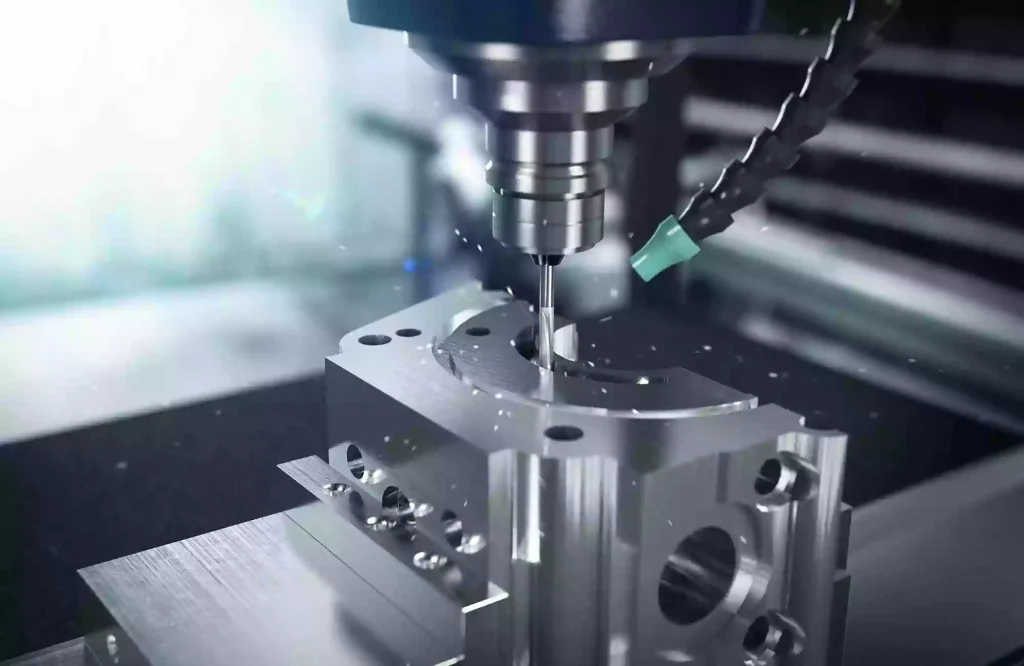
CNC Machining for Robotic Structural Components: From Design Review to Precision Manufacturing
Robotic structural components are not simply metal parts that need to be machined to drawing dimensions. Their geometry, weight, mechanical strength, mounting interfaces, and assembly relationships all influence how they should be manufactured.
A bracket may appear relatively simple, but its mounting holes may need to align with several adjoining components. A lightweight aluminum frame may contain deep pockets and thin walls that are difficult to machine without distortion. A joint housing may require multiple intersecting bores with tight positional tolerances to maintain the alignment of internal mechanical components.
These requirements make robotic component manufacturing a process-planning challenge as much as a machining challenge.
At Xtmade, we approach custom robotic component manufacturing from the perspective of the finished part and its functional requirements. Starting with customer-provided engineering drawings, CAD files, samples, and specifications, we evaluate material, geometry, machining access, workholding, tolerances, and inspection requirements before determining the production route.
This article examines the manufacturing considerations that influence CNC machining for robotic structural components, from initial design review to production and quality verification.
Why Robotic Structural Components Require Careful Manufacturing Planning
Robotic systems contain a wide range of structural and mechanical components. These parts support moving assemblies, connect actuators and transmission systems, maintain positional relationships, and protect internal mechanisms.
Unlike many conventional machined components, robotic structures often combine several functional requirements within a relatively compact design.
Structural strength and lightweight construction
Weight reduction is an important consideration in robotic design, particularly for moving assemblies such as arms, legs, and joints. Aluminum alloys such as 6061 and 7075 are commonly selected because they offer useful combinations of strength, weight, and machinability.
To reduce weight, designers may introduce pockets, hollow sections, ribs, and thin-wall structures. Although these features can reduce material usage, they also reduce workpiece rigidity during machining.
A component that is sufficiently rigid in its assembled condition may become much less stable after substantial material has been removed from the original billet.
Precision at connecting and mounting interfaces
Robotic components rarely function independently. They are assembled with bearings, shafts, actuators, fasteners, sensors, and other mechanical elements.
Consequently, the manufacturing requirements extend beyond individual dimensions. Hole positions, bore alignment, mounting-face flatness, perpendicularity, and concentricity may all affect final assembly.
For example, a mounting hole can meet its specified diameter while still being incorrectly positioned relative to the component’s primary datum. This distinction is particularly important when several components must be assembled into a mechanically aligned structure.
Complex geometry within limited machining space
Compact robotic designs often contain intersecting holes, narrow slots, recessed mounting features, internal cavities, and angled surfaces.
These features can restrict tool access and make workholding more complicated. A tool may be able to reach a surface geometrically but still lack sufficient clearance for the holder, spindle, or surrounding fixture.
The machining process must therefore account for the complete tool assembly and cutting direction, rather than considering the cutting tool alone.

Start With the Drawing: What We Evaluate Before Machining
A reliable manufacturing process begins before the workpiece is placed on the machine. The engineering drawing and 3D model provide the information needed to determine whether the component can be machined efficiently and consistently.
At Xtmade, the initial manufacturing review focuses on several interconnected areas.
Material and Raw Stock Selection
The specified material affects cutting conditions, tool selection, machining allowance, and potential deformation.
For example, 6061 and 7075 aluminum may both be suitable for robotic structural components, but they do not have identical mechanical properties or machining behavior. Their temper conditions and intended applications should also be considered.
For steel components, the specified grade and heat treatment condition influence cutting loads and the sequence of machining operations. If a component requires heat treatment, the process plan should account for possible dimensional changes and whether subsequent finishing operations are necessary.
Raw stock dimensions also matter. An unnecessarily large machining allowance increases material removal and machining time, while insufficient allowance may make it difficult to clean up all surfaces or compensate for stock variation.
We therefore review the material specification, stock dimensions, and finished geometry together before confirming the machining route.
Datum Structure and Critical Dimensions
Not all dimensions on a robotic component have the same functional importance.
Some dimensions define the overall envelope, while others determine how the component connects to neighboring structures. The latter often require more careful control.
During drawing review, we identify:
- Primary and secondary datum references.
- Critical mounting holes and threaded features.
- Bearing seats and shaft interfaces.
- Flatness and perpendicularity requirements.
- Hole position and concentricity requirements.
- Dimensions affected by subsequent surface treatments.
This review helps establish which surfaces should be machined first and which features should share a common setup.
If two holes must maintain a precise positional relationship, machining them from unrelated setups may introduce unnecessary positioning uncertainty. Where the geometry permits, completing these features from a common datum and setup can improve their relative accuracy.
Tool Accessibility and Machining Feasibility
A 3D model may contain features that appear straightforward in the design environment but are difficult to produce using conventional cutting tools.
Examples include narrow internal channels, deep pockets with small corner radii, intersecting bores, and recessed surfaces surrounded by high walls.
We evaluate whether the required tool diameter, cutting length, and holder clearance are compatible with the available machining space.
For deep features, the ratio between tool length and diameter is particularly important. Excessive tool overhang reduces rigidity and increases the risk of vibration and dimensional deviation.
Where a feature creates a significant manufacturing constraint, we assess alternative toolpaths, machining directions, or possible design adjustments without changing the component’s intended function.
Tolerance and Surface Finish Requirements
A drawing should distinguish between functional tolerances and general dimensional requirements.
Applying unnecessarily tight tolerances to every feature can increase machining time, inspection requirements, and overall manufacturing cost without improving the component’s actual performance.
During engineering review, we pay particular attention to tolerances associated with mating surfaces, bearing interfaces, locating features, and precision hole patterns.
Surface finish requirements should also be considered in relation to their function. A bearing seat, sealing surface, mounting face, and non-functional exterior surface may require different machining and inspection approaches.
This distinction helps ensure that manufacturing effort is concentrated on the features that matter most.
Planning the Machining Route Around Part Geometry
Once the drawing requirements are understood, the next step is to determine how each feature will be machined.
The objective is not to use the most complicated machine available. It is to select a process that provides adequate tool access, stable workholding, and reliable dimensional control without introducing unnecessary operations.
Establishing the Machining Datum
The machining datum should be selected according to the component’s functional reference surfaces and the relationship between its critical features.
For a plate-like component, a stable reference face may serve as the primary datum. For a housing with several mounting interfaces, the datum may need to be established around a machined base surface and a locating bore or reference feature.
Once the datum is established, the machining sequence should preserve that reference as much as possible.
Repeatedly changing the positioning reference can introduce errors between operations. This is particularly important for robotic components containing multiple mounting holes or intersecting bores.
Roughing, Semi-Finishing, and Finishing
The order in which material is removed has a direct influence on dimensional stability.
For components machined from solid aluminum stock, roughing may remove a substantial portion of the original material. If one side is machined completely before the opposite side, the remaining structure may become unevenly stressed and lose rigidity.
A more balanced machining sequence may involve removing material from different regions in stages, retaining temporary support where necessary, and leaving a controlled finishing allowance.
A typical process may include:
Rough machining: Remove the majority of excess material while maintaining sufficient stock for subsequent operations.
Semi-finishing: Establish the main geometry, refine reference surfaces, and prepare the component for final machining.
Finishing: Machine critical dimensions, mounting interfaces, and specified surface features after the component has reached a more stable condition.
The exact sequence depends on the material, component geometry, machining allowance, and tolerance requirements. For certain components, additional stress-relief or intermediate inspection may also be considered.
3.3 Choosing Between Three-Axis, Four-Axis, 3+2, and Five-Axis Machining
The number of machine axes should be determined by the actual geometry and required machining movements.
Three-axis machining is suitable for components with accessible planar surfaces, conventional pockets, slots, holes, and external profiles. Many mounting plates, brackets, and support structures can be manufactured efficiently using this approach.
Four-axis machining is useful when features are distributed around a rotational axis or when the workpiece needs to be indexed to different angular positions. It can reduce manual repositioning for components with circumferential holes or multiple side features.
3+2 machining is suitable for parts containing multiple fixed-angle surfaces, inclined holes, and different machining orientations. The rotary axes position the workpiece or tool at the required angle, while the three linear axes perform the cutting operation.
Five-axis simultaneous machining becomes more relevant when the tool orientation must change continuously along a complex surface or spatial toolpath. It can be useful for certain freeform housings and intricate structural profiles.
The important distinction is that a component with several angled surfaces does not automatically require simultaneous five-axis machining. If those surfaces can be accessed through fixed angular positioning, a 3+2 approach may provide a more practical manufacturing solution.
Turning and Mill-Turn Operations for Rotational Components
Not every robotic component should be manufactured primarily through milling.
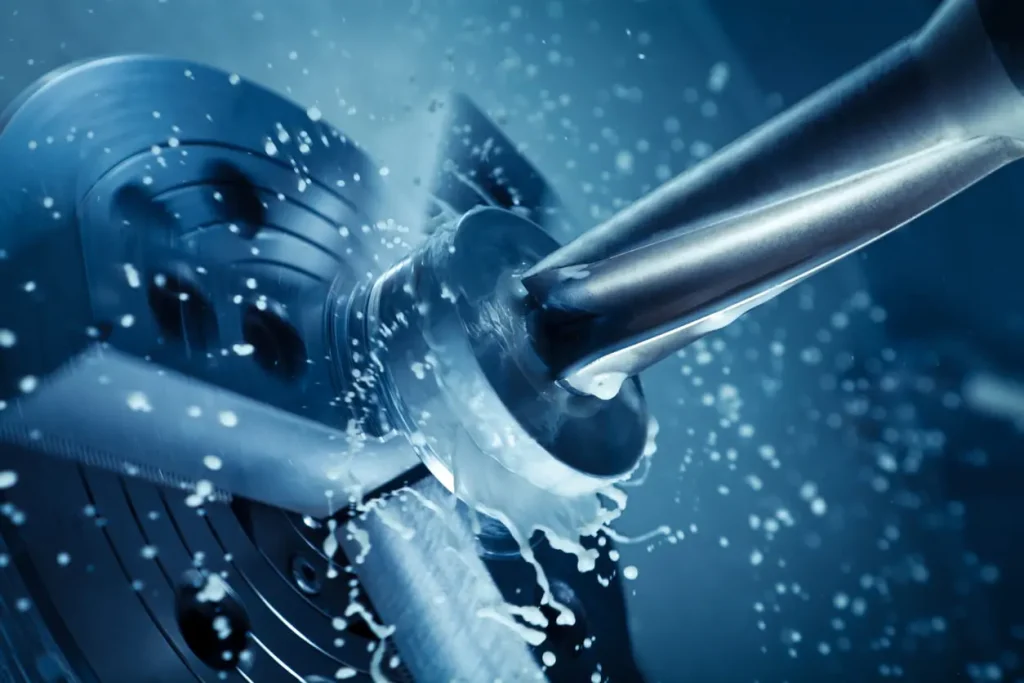
Shafts, pins, bushings, sleeves, and flange-like components often contain rotational features that are more efficiently produced by turning.
If these components also require cross-holes, keyways, flats, or other milled features, a mill-turn process may reduce the number of separate setups.
For small bar-fed components with suitable geometry and production quantities, Swiss-type turning may also be considered.
When selecting between conventional turning, Swiss-type machining, and mill-turn operations, we consider component dimensions, length-to-diameter ratio, feature distribution, tolerance relationships, and production volume.
Manufacturing Challenges in Robotic Components and How to Control Them
The most difficult machining problems often occur where lightweight design, complex geometry, and tight tolerances overlap.
The following issues deserve particular attention during process planning and production.
Thin-Wall Distortion in Lightweight Aluminum Structures
Thin-wall distortion is one of the main concerns when machining lightweight robotic frames and housings.
As material is removed, the remaining structure becomes less rigid. Cutting forces can cause the wall to deflect away from the tool, resulting in an inaccurate machined surface. Once the cutting force is removed, elastic recovery may cause the wall to move again.
Clamping pressure can create a similar problem. A thin section may be dimensionally correct while held in the fixture but change shape after unclamping.
We address this risk through a combination of machining sequence, workholding, and cutting-condition adjustments.
First, the machining plan should avoid removing too much material from one region while leaving other areas completely untouched. Balanced material removal helps maintain structural support during machining.
Second, clamping points should be positioned around sufficiently rigid areas. Excessive clamping force should be avoided, particularly on thin sections and unsupported walls.
Third, finishing operations should be performed after the main geometry has been established and the component has reached a more stable condition.
For particularly flexible structures, additional support or dedicated fixtures may be required.
Deep Cavities and Restricted Chip Evacuation
Deep pockets and internal cavities are common weight-reduction features in robotic structures.
However, the deeper the cavity becomes, the more difficult it may be to maintain tool rigidity and remove chips from the cutting area.
Long-reach tools are more susceptible to vibration and deflection. Meanwhile, chips can accumulate around the tool, become recut, and damage the machined surface.
The machining strategy should therefore consider more than the required cutting depth.
Tool diameter, overhang, flute length, step-down depth, and chip evacuation direction all affect process stability.
Where the geometry permits, roughing and finishing should be separated. Suitable toolpaths can also reduce unnecessary tool engagement and improve access for coolant or compressed air.
For deep and narrow features, the smallest possible tool is not always the best option. A larger tool with sufficient clearance may provide better rigidity and more stable material removal.
Intersecting Holes and Precision Bore Alignment
Joint housings, transmission supports, and connection structures may contain several intersecting or closely positioned bores.
These features often have a direct relationship with bearings, shafts, bushings, or other assembled components.
The main challenge is maintaining the dimensional and positional relationship between the bores, rather than simply producing each hole to its nominal diameter.
If the holes are machined from different setups, positioning errors can accumulate. Tool deflection and changes in cutting conditions may also affect bore geometry.
For critical bore systems, the machining sequence should establish a consistent reference and minimize unnecessary repositioning.
Depending on the tolerance requirements, finishing may involve precision boring, reaming, or other suitable operations. The final method should be selected according to the required diameter, geometric tolerance, material, and surface finish.
Inspection should verify the relevant bore dimensions and their relationship to the drawing datums.
Complex Mounting Faces and Multi-Directional Features
Some robotic components contain mounting surfaces oriented in different directions.
If these surfaces are not accurately positioned relative to one another, assembly gaps, angular deviations, or alignment problems may occur.
A common manufacturing challenge is determining which surfaces should be completed in the same setup and which can be machined after repositioning.
Where possible, critical mating features should be machined from a common reference. If multiple orientations are unavoidable, the locating method and datum transfer need to be carefully controlled.
Four-axis or 3+2 machining can reduce manual repositioning for suitable geometries. However, the fixture must still provide sufficient rigidity and repeatable positioning.
Burrs and Edge Conditions Around Small Features
Small holes, intersecting slots, and thin edges can produce burrs during milling and drilling.
In robotic assemblies, burrs may interfere with component seating, fastener installation, or the movement of adjacent mechanical elements.
Deburring should therefore be included in the manufacturing plan rather than treated as an optional final cleanup operation.
For small internal features, access may be restricted, making complete burr removal difficult. The drawing should clearly identify functional edges, sharp-edge requirements, and any areas where edge breaks are permitted.
Material Selection and Machining Considerations
Material selection is closely connected to structural performance, weight targets, and manufacturing requirements.
For robotic components, aluminum alloys are widely used, but steel and engineering plastics may also be appropriate depending on the function of the part.
Aluminum Alloys: 6061 and 7075
6061 aluminum is frequently used for brackets, housings, mounting structures, and other machined components. It offers a useful combination of machinability, strength, and corrosion resistance.
7075 aluminum provides higher strength and is often considered for components with more demanding mechanical requirements.
From a machining perspective, both materials require suitable cutting tools, effective chip evacuation, and attention to thin-wall stability.
The actual process should account for the material temper, component geometry, machining allowance, and required surface finish.
For components requiring anodizing, the machining process should also account for the finishing allowance and the effect of coating thickness on critical dimensions.
Carbon and Alloy Steels
Steel may be selected for components that require higher strength, wear resistance, or load-bearing capacity.
Grades such as 45 steel and 40Cr may be used in certain mechanical and transmission-related structures.
Compared with aluminum, steel generally produces higher cutting loads and requires different tooling and cutting conditions.
If the component undergoes heat treatment, the manufacturing sequence must account for possible distortion and changes in machinability. Depending on the final requirements, some dimensions may need to be finished after heat treatment.
Engineering Plastics and Lightweight Materials
PEEK, POM, and other engineering plastics may be used in selected robotic components where electrical insulation, low friction, chemical resistance, or reduced weight is required.
Unlike metals, plastics can be more sensitive to temperature changes and clamping pressure. Excessive cutting heat or an unsuitable fixture may cause dimensional changes, deformation, or burr formation.
Magnesium alloys may also be considered in lightweight structural applications, but their machining requires specific chip-handling and fire-prevention measures. They should not be treated as ordinary aluminum machining materials.
Material selection should always be based on the component’s functional requirements and the applicable technical specifications.
Surface Finishing and Dimensional Control After Machining
CNC machining is not always the final manufacturing operation. Many robotic structural components require surface treatments to meet corrosion-resistance, wear, appearance, or assembly requirements.
The selected finishing process can affect both the surface and the final dimensions.
Anodizing for Aluminum Components
Anodizing is commonly used for aluminum components to improve surface protection and provide different appearance options.
However, the coating changes the surface dimensions. For components with precision bores, threaded features, bearing seats, and mating interfaces, the coating allowance should be considered before machining.
Not every surface needs to receive the same treatment. Some functional areas may require masking or a different finishing specification according to the drawing and assembly requirements.
Surface Preparation and Edge Quality
Machined surfaces should be prepared according to the required finishing process.
Tool marks, scratches, burrs, and sharp edges may affect coating appearance or create local defects. For visible exterior components, surface consistency may also be important.
The required surface preparation should be defined before production so that machining, deburring, and finishing operations are coordinated.
Dimensional Verification After Surface Treatment
For precision components, inspection before finishing may not fully represent the final condition.
Coating thickness, heat treatment, and other secondary operations can influence dimensions. Critical features should therefore be checked at the appropriate stage according to the drawing and customer inspection requirements.
Where necessary, machining allowances and masking requirements should be agreed upon during the initial engineering review.
How We Control Quality Throughout the Manufacturing Process
For robotic structural components, quality control should not depend entirely on the final inspection.
Dimensional errors can originate during setup, material removal, tool wear, or secondary processing. If these issues are only discovered after all operations have been completed, corrective work becomes more difficult.
Our manufacturing approach considers inspection requirements at several stages.
Material and Drawing Verification
Before machining, material specifications and drawing requirements should be confirmed.
This includes checking material grades, stock dimensions, drawing revisions, critical tolerances, and any required material documentation.
For projects with specific traceability requirements, the applicable material certificates and identification records should also be confirmed.
First-Article Inspection
The first completed component provides an opportunity to verify whether the selected process produces the required geometry.
Inspection should focus on critical dimensions, datum relationships, hole positions, mounting interfaces, and specified surface conditions.
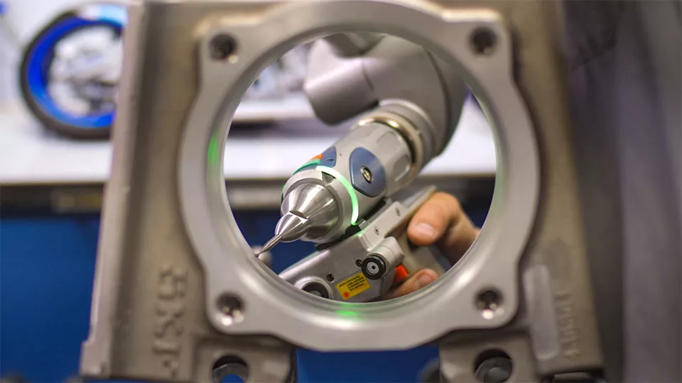
For complex components, CMM inspection may be used to verify geometric characteristics that cannot be adequately assessed using basic dimensional tools.
If the first article reveals deviations, the machining sequence, fixture positioning, tool offsets, or other relevant process variables should be reviewed before production continues.
In-Process Inspection
In-process inspection helps identify changes before they affect a large number of components.
Depending on the part and production requirements, inspection may include:
- Critical dimensions after rough machining.
- Reference surfaces before subsequent setups.
- Bore sizes and hole positions.
- Thin-wall dimensions after unclamping.
- Tool wear and machining consistency.
- Features affected by secondary processing.
For components with tight positional requirements, maintaining consistent datum references between machining and inspection is particularly important.
Final Inspection and Documentation
Final inspection verifies that the completed component meets the agreed drawing and technical specifications.
Depending on the project requirements, inspection may involve CMM measurements, dimensional reports, surface roughness checks, and other applicable verification methods.
Where required, first-article inspection reports, material documentation, and inspection records can be prepared according to the agreed quality requirements.
From Prototype Parts to Repeat Production
Manufacturing requirements change as a robotic product moves from initial development to repeated production.
A process that works well for a single prototype may not be the most efficient option for hundreds or thousands of components.
The manufacturing strategy should therefore evolve with the design and production volume.
Prototype Manufacturing: Flexibility Comes First
During early development, design changes are common. Hole positions, wall thicknesses, mounting interfaces, and material specifications may be revised after assembly or functional testing.
At this stage, CNC machining provides flexibility because components can be manufactured directly from updated CAD models and drawings without immediately requiring dedicated production tooling.
The priority is to verify the geometry, fit, and functional dimensions while maintaining sufficient flexibility for engineering changes.
Low-Volume Production: Improve Repeatability
Once the design becomes more stable, the manufacturing process should be made more repeatable.
This may involve standardizing workholding methods, machining datums, tool configurations, and CNC programs.
For components with similar geometry, common fixture concepts or machining strategies may reduce setup time. However, shared tooling should not compromise the positioning requirements of individual parts.
First-article results and production inspection records can also be used to refine the process before larger orders are scheduled.
Higher-Volume Production: Evaluate Process Economics
When production quantities increase and the design becomes more standardized, alternative manufacturing methods may become economically viable.
Depending on component geometry and order volume, the raw material may shift from solid billet to forging, casting, or die-cast blanks.
CNC machining can then focus on critical mounting surfaces, precision bores, threaded features, and other areas that require tighter tolerances.
For suitable rotational components, automated turning or Swiss-type machining may improve production efficiency.
The decision to adopt near-net-shape manufacturing should consider tooling investment, material utilization, dimensional requirements, and expected production volume. It is not automatically the most economical choice for every robotic component.
Manufacturing Robotic Components at Xtmade
Robotic component manufacturing requires coordination between drawing interpretation, process planning, machining, and inspection. A capable manufacturing partner needs to understand how the component’s geometry and functional features influence each stage of production.
Xtmade is a custom robotic CNC machining factory based in Shenzhen, China, with approximately 120,000 sq. ft. of manufacturing facilities. We manufacture custom components based on customer-provided drawings, CAD files, samples, and technical specifications.
Our manufacturing capabilities include three-axis, four-axis, and five-axis CNC machining, turning and mill-turn operations, and large-gantry machining.
For robotic structural components, our engineering team evaluates the part before production, with particular attention to:
Manufacturing feasibility: Reviewing material, geometry, tolerances, machining access, and workholding requirements.
Machining process planning: Selecting suitable machining methods and sequencing operations around the component’s critical features.
Precision machining: Matching machining methods to dimensional and geometric requirements, with standard machining tolerances generally around ±0.01 mm and precision work potentially reaching ±0.005 mm, subject to part geometry and production conditions.
Dimensional inspection: Using appropriate measurement methods, including CMM inspection where required, to verify critical dimensions and geometric characteristics.
Production coordination: Organizing manufacturing and inspection requirements to support prototypes, small batches, and repeat orders.
Our engineering team brings more than 20 years of industry experience. Rather than treating every robotic component as a standard milling job, we assess its actual manufacturing requirements and determine a process that balances precision, machinability, and production efficiency.
If you are developing robotic arms, joint assemblies, structural frames, precision housings, or other custom robotic components, you can send your engineering drawings or CAD files to Xtmade for a manufacturing review.
We can evaluate the material, geometry, tolerances, and machining requirements to determine a suitable CNC manufacturing approach for your project.