Hoe om te gaan met vervorming bij de bewerking van dunwandige onderdelen van 7075-aluminiumlegering: oplossingen voor procescontrole en werkstukopspanning van Xtmade
7075 aluminum alloy, prized for its high strength-to-weight ratio and excellent mechanical properties, is widely used in aerospace, precision equipment, and the manufacturing of high-performance structural components. However, for parts characterized by high material removal rates, thin walls, and asymmetrical geometry, the primary challenge lies not in the material itself, but in managing stress release, clamping-induced deformation, and the impact of cutting forces during the machining process.
This is particularly true for thin-walled support structures, deep cavities, and open-style configurations created through extensive material removal. Even if the initial blank possesses sufficient rigidity, the part’s inherent structural integrity diminishes as the machining allowance is reduced. Cutting forces, clamping forces, and residual stresses can all trigger deformation, causing critical dimensions and geometric tolerances to fall outside of specified requirements.
In Xtmade’s precision CNC machining operations, we do not rely solely on finishing tools or reduced cutting parameters when handling such components. Instead, we implement a comprehensive control strategy that encompasses material stress release, machining datums, workholding methods, specialized support tooling, and optimized toolpaths.
Drawing on our experience in machining low-rigidity, thin-walled 7075 aluminum alloy components, this article explores how we analyze the root causes of deformation and enhance machining stability through process optimization.
Why are thin-walled 7075 aluminum alloy parts prone to deformation during machining?
Deformation in thin-walled parts during machining is rarely the result of a single factor; rather, it stems from the combined effects of internal material stress, structural rigidity, clamping forces, and cutting forces.
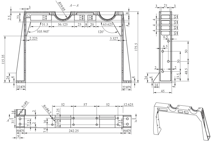
Consider a type of 7075 aluminum alloy structural component we have processed: the part measures approximately 282 mm in length and 175.5 mm in width, with an initial blank thickness of about 31 mm. Following the removal of a significant amount of material, the final wall thickness in certain areas is reduced to just 2 mm—an overall material removal rate exceeding 95%.
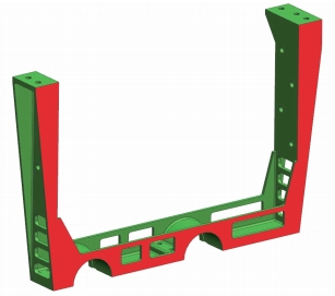
The component features an open-style structure with supporting legs on either side. Once machining is complete, the structural rigidity between these legs is substantially diminished. Under these conditions, even relatively minor cutting forces can trigger localized vibration, elastic deformation, or dimensional spring-back.
High Material Removal Rate Leads to Internal Stress Redistribution
During the rolling, heat treatment, and subsequent processing of 7075 aluminum alloy blanks, certain internal residual stresses may develop.
When more than 95% of the original material must be removed to produce a part, the initial state of stress equilibrium is disrupted as material is progressively taken away. This is particularly significant when machining components with large cavities, deep slots, or thin-walled structures; because the amount of material removed and the resulting changes in structural rigidity vary across different regions, localized stress redistribution often occurs.
If a part is machined directly from the blank to its final dimensions, internal stresses may be released gradually throughout the process—manifesting as the warping of walls, the spreading or contraction of support legs, or overall dimensional changes in the finished component. For thin-walled parts requiring a high material removal rate, it is preferable to employ a multi-stage approach—combining rough machining, the retention of machining allowances, and intermediate aging treatments—rather than attempting to remove all the excess material in a single operation.
Thin-walled structures lack sufficient rigidity and are highly susceptible to the influence of cutting forces.
The flexural rigidity of a thin-walled structure is closely linked to its wall thickness. As the wall thickness decreases, the component’s ability to resist cutting forces drops rapidly.
For instance, a structure with a final wall thickness of only 2 mm might retain adequate overall structural support during the roughing stage; however, as internal material is removed and openings are created in the supporting structures on either side, the original rigid support is compromised, making the component more prone to elastic deformation.
If the cutting tool exerts a significant lateral force against a thin wall, the component may shift or vibrate during machining. Even if the part partially regains its original shape once the tool is withdrawn, the elastic deflection that occurred during the cutting process can still result in dimensional inaccuracies.
This is precisely why the machining parameters used for standard aluminum alloy parts cannot be directly applied to thin-walled components. Factors such as tool selection, cutting direction, depth of cut, and the continuity of the toolpath must all be adjusted based on the specific support conditions of the part.
Traditional Clamping Methods Can Induce Additional Deformation
For structurally weak or low-rigidity components, the clamping process itself can become a source of deformation.
Applying significant clamping force—via a vise or clamps—to thin-walled sections can force a part to conform to a specific shape while secured. Although the dimensions may appear to meet specifications during machining, the part will undergo elastic springback once the clamping force is removed, altering its final geometry.
Furthermore, when thin-walled parts require multiple reorientations or repositioning, the lack of a consistent datum across operations can easily lead to positioning errors. This, in turn, compromises the dimensional relationships between features on opposite sides, mounting surfaces, and critical hole locations.
When developing a machining strategy for thin-walled components, two key challenges must be addressed: minimizing forced deformation caused by clamping, and ensuring consistent positioning across multiple setups.
From Roughing to Finishing: Staged Relief of Internal Stress in 7075 Aluminum Alloy
For 7075 aluminum alloy structural components requiring high material removal rates, we do not combine roughing and finishing into a single, continuous operation. Instead, we release internal stress in stages, aligned with the structural evolution of the part. In the machining process for the aforementioned thin-walled structural components, we employed a strategy consisting of three distinct stages of roughing, interspersed with an intermediate aging treatment.
Initial Rough Machining: Establishing a Foundation for Overall Processing
The first step involves uniform rough machining of the workpiece blank, prioritizing the removal of the bulk of the excess material while leaving an allowance of approximately 3 mm for subsequent machining stages.
The primary focus at this stage is not to maximize the material removal rate, but rather to control the amount of material removed from various areas, ensuring that no single side or localized section loses its structural support prematurely.
Once rough machining is complete, an initial aging treatment is performed. This allows internal stresses—gradually released during the machining process—to further stabilize, creating a more stable foundation for subsequent machining operations.
Second Rough Machining: Continued Material Removal and Structural Change Management
Following the first aging treatment, the part is re-clamped for a second stage of rough machining, focusing on the primary cavities and structural zones, with the remaining machining allowance controlled to approximately 2 mm.
As material is further removed, the local rigidity of the part changes significantly. Consequently, this stage requires not only the control of cutting forces but also careful attention to the forces exerted during clamping.
Clamping methods are adjusted based on the support points of the part to avoid using excessive external force to secure it. For clamping positions requiring specific torque, torque wrenches are employed to ensure consistency and minimize variations caused by manual operation.
Once the second rough machining stage is complete, the part undergoes another round of aging treatment.
Third Rough Machining: Establishing Stable Conditions for Finish Machining
Following the initial two rounds of material removal and stress relief, a third stage of uniform rough machining is performed, further reducing the machining allowance to approximately 1 mm.
At this stage, the part closely resembles its final configuration, with variations in local wall thickness and support zones becoming more pronounced. We avoid concentrating significant material removal in any single area, aiming instead to maintain a balanced state of internal stress throughout the component.
Once the third rough machining stage is complete, an intermediate aging treatment is scheduled.
It should be emphasized that this intermediate aging treatment is not merely an additional process step; rather, it serves to minimize dimensional changes during the subsequent finish machining phase—changes that would otherwise arise from the redistribution of residual stress. The specific treatment method, temperature, and holding duration are determined based on the material’s condition, heat treatment requirements, and the technical specifications of the part.
Optimizing Clamping Methods: Reducing Clamping-Induced Deformation in Thin-Walled Parts
Following the completion of multi-stage rough machining, the next challenge to address is the clamping strategy for the finishing process.
For thin-walled components featuring inclined side edges and an open structure, conventional clamping using pressure plates often leads to localized stress concentrations. Given the relatively low rigidity of the supporting legs on either side, even the slightest unevenness in clamping force can compromise the part’s precise positioning and geometric integrity.
Our approach involves maximizing the effective support area, leveraging the component’s inherent structural features for positioning, and minimizing the mechanical clamping force applied directly to the thin-walled sections.
Securing Parts via Adhesive Bonding
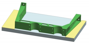
During the finish machining of the first side, the designated mounting surface of the part is used as a reference datum, and the workpiece is secured onto a specialized fixture plate.
Unlike traditional mechanical clamping—which uses pressure plates—this approach employs “302” adhesive as an auxiliary securing method, thereby minimizing the direct application of clamping force onto the thin-walled structure.
First, based on the actual geometry and orientation of the part, V-shaped positioning features are machined into the fixture plate. These features, which stand approximately 1 mm high, engage with the inclined edges on both sides of the part to ensure stable, precise orientation.
During setup, the inclined edges of the workpiece are brought into full contact with the V-shaped positioning surfaces on the fixture; the workpiece is then secured in place by applying adhesive along the contact interfaces between the part and the fixture.
By combining V-shaped positioning features with adhesive bonding, the workpiece’s movement is constrained in multiple directions, while the significant localized pressure—often associated with traditional clamping methods—is avoided in the thin-walled regions.
It should be noted that using adhesive bonding for workholding does not mean that mechanical forces can be disregarded. Factors such as the contact area between the workpiece and the fixture, the condition of the adhesive layer, the curing time of the adhesive, and the loads generated during subsequent machining operations must all be evaluated in advance. For processes involving high cutting loads, it is also necessary to verify that the bonding strength is sufficient to meet the requirements.
Machining After Reorientation: Maintaining a Consistent Datum
Once the first side has been machined, the part must be flipped to allow for the machining of the opposite side.
The critical focus during this stage is ensuring consistency in the datum (reference) used for positioning across successive operations. Since all six external surfaces of the part require machining, the datum relationship must be clearly defined for each reorientation; this prevents the accumulation of dimensional errors that could otherwise arise from repeated repositioning.
By employing a positioning strategy that corresponds to the one used for the first side, we machine the second side—completing the external profile, mounting surfaces, and the overall thickness of the part.
Upon completion of this step, the part’s external dimensions meet the design specifications. The remaining work focuses primarily on the precision machining of internal cavities and thin-walled structures.
Develop specialized split-type support tooling to enhance stability during internal cavity machining
Once the external profile of a part has been machined, the processing of its internal cavity becomes one of the most critical stages in the entire manufacturing process.
At this point, the vast majority of the material has been removed, leaving the thin-walled sections with very limited structural rigidity. Relying solely on standard fixtures to secure the part can easily lead to localized vibration or structural deformation during machining. Consequently, it is necessary to design specialized support tooling specifically for the final-stage machining of the internal cavity.
Why use a modular (split-type) fixture design?
For large, thin-walled components, designing the entire support fixture as a single, integrated unit would not only consume a significant amount of material but also increase both machining costs and the time required for fixture fabrication.
We have adopted a modular design, breaking the internal cavity support fixture down into three separate components. These three parts are configured to align with the component’s external geometry, base structure, and side profiles—ensuring the necessary support surface area while simultaneously simplifying the fabrication, installation, and subsequent adjustment of the fixture.
Designing Support Clearances Based on Actual Part Dimensions
Since the external dimensions of the parts have already been machined to design specifications, the internal dimensions of the fixture cannot be based solely on the theoretical dimensions of the parts.
In our fixture design, we use the actual external geometry of the parts as a reference, incorporating a clearance of approximately 0.06–0.10 mm per side. This ensures that the parts can be loaded smoothly while guaranteeing full contact between the side and bottom surfaces of the parts and their corresponding support surfaces.
If the fixture clearance is too large, the parts may still shift under the influence of cutting forces; conversely, if the clearance is too small, assembly interference may occur, introducing unwanted stress. Fixture design must account not only for dimensions but also for ease of assembly, the contact area of the supports, and the actual cutting loads.
Local Reinforcement of Weak Areas
For thin-walled structural components, overall support does not necessarily guarantee sufficient rigidity in every localized area.
In such parts, holes with low structural rigidity are particularly prone to deformation and vibration. If these areas lack effective support during machining, the cutting forces exerted by the tool can trigger localized vibration, which compromises the quality of the machined surface and dimensional stability.
To address this, we identify weak areas during the fixture design and machining preparation phases, and incorporate auxiliary supports tailored to the specific structure.
In the aforementioned machining strategy, specific holes can be temporarily reinforced using suitable filler materials—such as moldable putty or fire-resistant sealing compound—or by employing improvised fillers, like a damp towel that is tightened into place after being soaked. This helps to mitigate localized vibration.
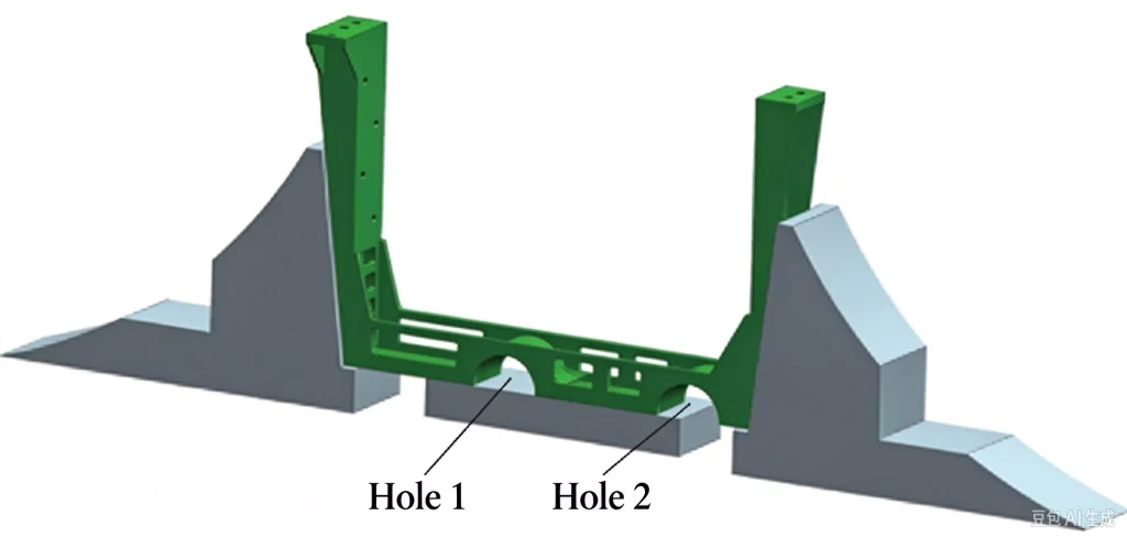
Such auxiliary supports must be evaluated based on factors including the material, cutting fluid, the tool’s range of motion, and chip evacuation conditions; they must neither interfere with the normal operation of the tool nor allow any filler material to enter the machining zone.
By combining modular fixturing with localized auxiliary support, it is possible to enhance the overall machining stability of thin-walled components during the final stages, without relying on excessive clamping force.
Optimizing CNC Toolpaths to Reduce Deformation Caused by Cutting Forces
Even when the workholding setup provides sufficient support, an ill-conceived toolpath can still cause thin-walled structures to vibrate or undergo elastic deformation due to cutting forces.
Therefore, once the clamping strategy has been finalized, it is essential to specifically optimize the toolpaths used for machining internal cavities.
For such components with low structural rigidity, the primary focus of toolpath planning is not merely to shorten machining time, but to ensure the cutting process remains as smooth as possible, preventing sudden fluctuations in cutting forces.
Prioritize reciprocating toolpaths along the length of the part
When machining internal cavities, it is preferable to employ a reciprocating cutting strategy aligned with the length of the part, thereby minimizing unnecessary lateral movement.
The primary objective is to maintain a relatively consistent direction for the main cutting forces, preventing frequent shifts in force orientation and reducing the risk of thin-walled structures being subjected to alternating loads.
Naturally, the specific toolpath direction must be determined by considering factors such as the part’s support points, wall thickness distribution, and the tool entry direction; it should not be assumed that a single, uniform machining direction is suitable for all thin-walled components.
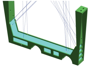
Reducing Sharp Turns in Toolpaths and Sudden Fluctuations in Cutting Load
When a cutting tool frequently changes direction at corners, instantaneous fluctuations in cutting load can occur. This is particularly problematic near thin-walled structures, where such changes are more likely to induce vibration and localized deformation.
Therefore, during the programming phase, we aim to minimize unnecessary sharp turns and interruptions in the toolpath. By optimizing the transitions between adjacent toolpaths, we ensure more continuous tool motion.
Furthermore, based on the wall thickness and support conditions of different areas, we carefully configure parameters such as depth of cut, radial width of cut, and feed rate—ensuring that excessive cutting loads are avoided in regions with insufficient rigidity.
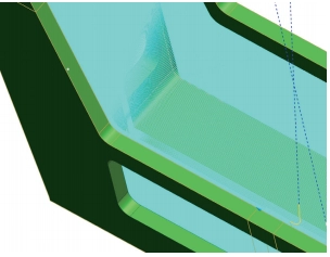
Controlling Tool Overhang to Enhance Machining Rigidity
When machining deep cavities or internal features, the tool overhang—the length of the tool extending from the holder—directly affects machining stability.
A longer tool overhang generally reduces the system’s flexural rigidity, making it more susceptible to vibrations and tool deflection during the cutting process.
Therefore, while ensuring the requirements for machining depth and clearance are met, we aim to minimize the tool overhang by selecting an appropriate tool diameter, flute length, and overall tool configuration.
For parts with complex internal cavities or those requiring multi-directional machining, the use of 4-axis or 5-axis capabilities allows for the optimization of tool orientation and approach angles. This reduces the need for redundant setups, thereby improving machining efficiency and positioning consistency.
It should be noted that 5-axis machining does not automatically eliminate the deformation of thin-walled components. Ultimately, machining quality is determined by the effective coordination of tool orientation, cutting parameters, workholding/support, and the inherent rigidity of the part itself.
Machining Results: Controlling Deformation of Thin-Walled Structures to Within 0.03 mm
By employing a multi-stage rough machining process combined with aging treatment, adhesive-based positioning, specialized modular fixtures, auxiliary support for structurally weak areas, and optimized toolpaths, we successfully resolved the primary deformation issues encountered during the machining of these 7075 aluminum alloy thin-walled components.
For this part, the design tolerance for critical dimensions is ±0.03 mm. Post-machining inspection focuses on the distance between the supporting legs on either side, the dimensions of the mounting surfaces, and other key geometric features.
Following machining, a Coordinate Measuring Machine (CMM) was used to conduct a full-dimensional inspection, verifying all critical dimensions and geometric characteristics.
The final inspection results confirm that all specified dimensions for this batch of parts meet the requirements set forth in the engineering drawings, with post-machining deformation controlled to within 0.03 mm.
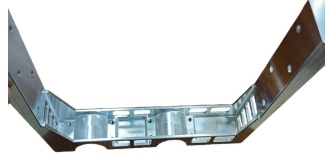
This machining process further demonstrates that for thin-walled aluminum alloy components—characterized by high material removal rates and insufficient structural rigidity—simply reducing cutting parameters cannot fundamentally resolve the issue of deformation. Only by integrating material stress control, clamping and positioning, auxiliary support, and toolpath planning can one achieve stable dimensional accuracy while maintaining machining efficiency.
How does Xtmade handle high-precision, thin-walled aluminum alloy parts?
At Xtmade, we approach the machining of thin-walled parts as a systematic process-control endeavor rather than a routine CNC-frezen task. Before production begins, we analyze the client’s CAD files, engineering drawings, and technical specifications—evaluating factors such as structural rigidity, wall-thickness distribution, material removal rates, machining datums, and critical tolerances.
For structures prone to deformation, we focus on the following key areas:
- Process Planning: We establish a sequence of roughing, semi-finishing, and finishing operations based on the raw material state and the volume of material to be removed. When necessary, we incorporate intermediate stress-relief steps to prevent structural deformation caused by concentrated material removal.
- Workholding and Positioning: We carefully select positioning datums, clamping methods, and support points to minimize the impact of clamping forces on thin-walled sections. For complex geometries, we can design custom fixtures or auxiliary supports.
- Tooling and Machining Parameters: We optimize tool selection, cutting parameters, and toolpaths—factoring in material hardness, wall thickness, machining depth, and tool overhang—to effectively manage cutting forces and minimize vibration.
- Dimensional Inspection and Quality Verification: Using equipment such as CMMs (Coordinate Measuring Machines), we verify critical dimensions, positional relationships, and geometric tolerances to ensure the final parts meet all client specifications.
Xtmade biedt customized precision aluminum CNC machining, with standard tolerances of ±0.01 mm and high-precision tolerances reaching ±0.005 mm. For thin-walled, deep-cavity, or complex parts, we assess the achievable precision based on the specific geometry, material, manufacturing process, and drawing requirements, rather than applying a one-size-fits-all tolerance guarantee.
If your project involves thin-walled 7075 aluminum alloy components, parts requiring high material removal rates, or other precision components with low structural rigidity, please send us your CAD files and engineering drawings. Our engineering team will evaluate the project in terms of manufacturing feasibility, workholding strategies, and process routing to help determine the most effective production solution.