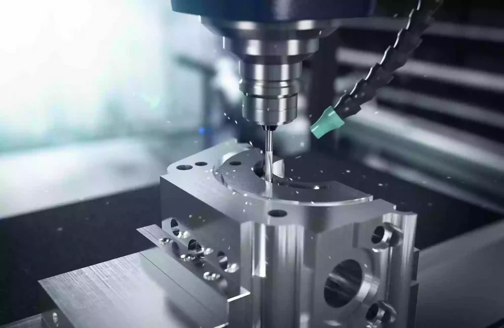
What is 3+2 Axis Machining?
When it comes to machining multi-sided parts, workshops usually face two extreme choices: either stick with a 3-axis machine and endure the constant manual flipping, part-realigning, wasted cycle time, and cumulative tolerance errors; or invest in an expensive simultaneous 5-axis mill and tackle the complex programming and collision simulation that comes with it.
This is where 3+2 axis machining comes in as the ultimate high-ROI sweet spot. The logic is straightforward: use the rotary axes to tilt and lock the workpiece into a specific angle, and then perform high-rigidity cutting just like a standard 3-axis machine.
Simply put, it solves one core problem: how to achieve “one-setup, multi-sided machining” using the simplest 3-axis programming and the most stable mechanical rigidity.
This article will break down 3+2 axis machining across 7 key dimensions: definition, working principle, machine configurations, process advantages, cost breakdown, technical comparison (3-axis vs. 3+2 vs. simultaneous 5-axis), and DFM (Design for Manufacturing) guidelines.
What is 3+2 Axis Machining?
Many people wonder why we call it “3+2” when the machine clearly utilizes five physical axes.
The name actually accurately reflects its underlying kinematics. 3+2 axis machining (commonly referred to in the industry as positional or indexed 5-axis) essentially separates spatial positioning from actual cutting into two distinct phases:
At the start of the process, the machine’s two rotary axes rotate to orient the workpiece or spindle head to the desired spatial angle. Once positioned, the rotary axes are mechanically or hydraulically clamped to ensure high-rigidity locking. During the subsequent cutting process, these rotary axes do not participate in any interpolating movement; the machining is carried out entirely by the X, Y, and Z linear axes, behaving exactly like standard 3-axis milling. Only after the current feature is finished will the rotary axes unlock, index to the next angle, and clamp again for the next cycle.
This is the fundamental dividing line between 3+2 and simultaneous 5-axis: simultaneous machining requires all 5 axes to dynamically interpolate and compensate while cutting, whereas 3+2 axis machining demands that the rotary axes remain completely static and rigidly locked during the cut.
Consequently, at the controller level, 3+2 axis is still programmed and executed as 3-axis machining. It merely leverages the spatial positioning capability of a 5-axis platform to streamline traditional 3-axis setups.
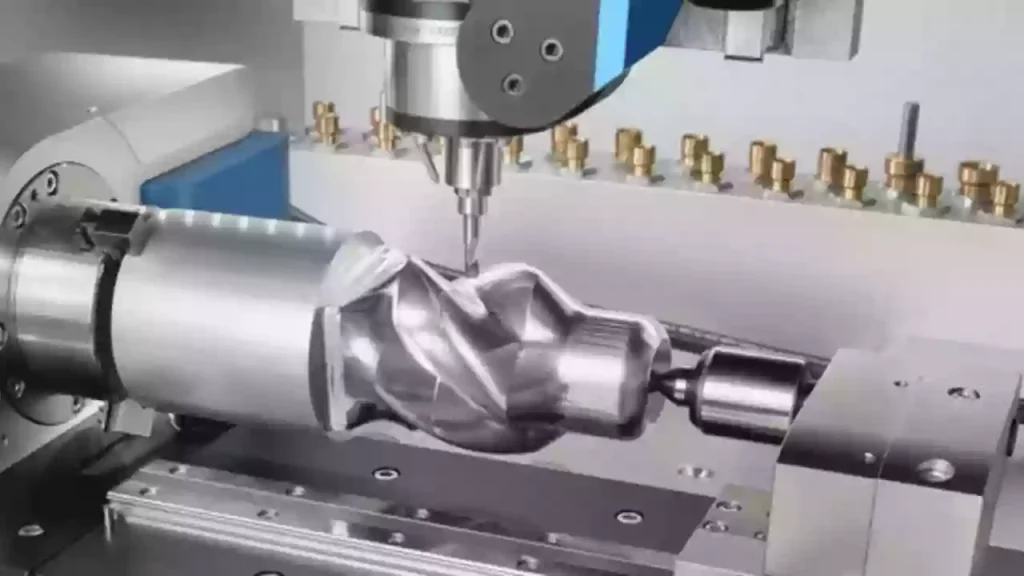
How 3+2 Axis Machining Works
To successfully execute 3+2 axis machining, the CNC controller, machine hardware, and CAM software must work in coordination through the following three steps:
Step 1: Coordinate System Transformation (TWP)
In standard 3-axis machining, the tool moves strictly within a fixed Work Coordinate System (WCS). Once the rotary axes tilt the workpiece, the original coordinate system is no longer perpendicular to the tool axis.
To resolve this, the CNC controller utilizes a coordinate transformation technology called Tilted Working Plane (TWP)—typically executed via the G68.2 command in FANUC or the PLANE function in Heidenhain.
The logic is straightforward: once the rotary axes complete their positioning, the controller uses mathematical matrices to establish a temporary, virtual 3-axis plane on the tilted surface. This allows the program to run standard X, Y, and Z instructions without requiring the controller to perform real-time, dynamic tool-center-point calculations as in simultaneous 5-axis machining.
Step 2: Mechanical Clamping of the Rotary Axes
The ability of 3+2 axis machining to handle heavy-duty cutting relies heavily on its physical clamping mechanism.
Once the rotary axes orient the workpiece to the target angle, the machine does not rely on the electromagnetic holding torque of the servo motors to resist cutting forces. Instead, high-pressure hydraulic or pneumatic brakes inside the rotary table or swivel head engage immediately. On high-rigidity machines, Curvic Couplings are often used for positive mechanical interlocking.
This rigid lock turns the rotary axes into a solid, static structure, allowing cutting vibrations and impact forces to be transferred directly into the machine bed casting to ensure process stability.
Step 3: CAM Path Planning and Transitions
In CAM software, the programming logic of 3+2 axis machining is based on plane-by-plane programming.The programmer only needs to define different machining planes and their corresponding tool axis directions. The post-processor then automatically inserts a safe transition sequence between these planes. The standard sequence of motion is:
Retract tool to safety height → Unlock and index rotary axes → Clamp rotary axes → Plunge and cut.
This logic prevents any collision between the tool, workpiece, and fixtures during rotary movements.
Machines and Equipment for 3+2 Axis Machining
In actual production, 3+2 axis machining is performed on CNC machines from top-tier global brands. Depending on the mechanical design, these machines generally fall into two main categories:
Category 1: Trunnion-Style 5-Axis Machines (Table-Table)
On a trunnion machine, the two rotary axes (usually the A and C axes) are integrated into the worktable. The spindle remains in a fixed vertical position while the workpiece tilts and rotates like a cradle. This is the most popular machine configuration for 3+2 axis machining because it offers superior cutting rigidity.
Haas Automation — UMC Series
Representative Models: Haas UMC-750 or UMC-500.
Key Features: These are highly popular 5-axis machines found in shops worldwide. Due to their affordability and user-friendly control systems, many workshops utilize them specifically as high-efficiency 3+2 axis machines to process manifolds, valve bodies, and multi-sided components.
DMG MORI — DMU Series
Representative Models: DMG MORI DMU 50.
Key Features: DMG MORI is an industry benchmark for precision. Their machines feature highly robust spindles and rigid bed designs, providing exceptional cutting stiffness when running heavy 3+2 positional roughing cycles.
Category 2: Swivel-Head 5-Axis Machines (Head-Head)
On a swivel-head machine, the worktable remains stationary. The two rotary axes (usually the B and C axes) are integrated into the spindle head. The spindle tilts the tool to the required angles while the table supports the weight. This style is ideal for machining very large, heavy components.
Okuma — MU Series
Representative Models: Okuma MU-5000V.
Key Features: As a premier Japanese machine builder, Okuma is renowned for high thermal stability and spindle rigidity. Once the swiveling head is locked into place for 3+2 machining, its rigidity easily rivals that of a standard 3-axis mill.
Mazak — VARIAXIS Series
Representative Models: Mazak VARIAXIS i-700.
Key Features: Known for exceptional multi-tasking capabilities. Mazak’s advanced Smooth CNC control offers excellent algorithmic support for coordinate system transformations (TWP), ensuring fast, fluid transitions between tilted planes.
Alternative Solution: Retrofitting a 3-Axis Machine
If a shop is on a budget and does not want to purchase a brand-new 5-axis machine, upgrading an existing 3-axis vertical machining center (VMC) is a practical route.The Approach: Install a high-quality 2-axis rotary table (or platter) onto the table of an existing 3-axis machine.Industry Standard Brands: Japanese rotary tables like Tsudakoma are widely used for this purpose, instantly giving a standard 3-axis mill 3+2 axis positioning capability.
Why Choose 3+2 Axis Machining?
Why is 3+2 axis machining so popular? It solves the exact pain points of 3-axis and simultaneous 5-axis in three simple points:
- One Setup, No Tolerance Stacking: Machining multiple sides on a 3-axis mill requires manual flipping 5 times, introducing setup errors. 3+2 does five sides in one setup—saving labor and eliminating cumulative tolerances.
- Shorter Tools, Higher Rigidity: By tilting the workpiece, the spindle gets closer to the cutting surface. This eliminates the need for long, flexible tools, allowing short, rigid tools for heavy cuts with zero chatter and better surface finishes.
- Simple Programming, Low Learning Curve: Simultaneous 5-axis programming requires complex collision avoidance; 3+2 is just standard 3-axis programming on tilted planes. Any 3-axis programmer can run it with almost zero extra training.
Cost and Economic Analysis
In the feasibility study of any manufacturing project, cost is a comprehensive financial model driven by Capital Expenditure (CapEx) and Operational Expenditure (OpEx).
First, regarding Capital Expenditure (CapEx), 3+2 axis machining offers remarkable capital efficiency. A high-end, imported simultaneous 5-axis machine typically commands a purchase price between $500,000 and $1,000,000. In contrast, a native 3+2 positional machine costs only around $100,000 to $150,000. Furthermore, retrofitting an existing 3-axis mill with a dual-axis rotary table drops the hardware entry barrier to a mere $20,000 to $30,000. This dramatically shortens the payback period and keeps the balance sheet stable for small-to-medium machine shops.
Second, there is a stark contrast in Software Licensing and Labor Overhead. Simultaneous 5-axis machining demands premium CAM software continuous modules, alongside highly compensated programmers capable of calculating complex dynamic clearances. Additionally, developing custom post-processors for continuous motion is a major upfront expense. On the other hand, 3+2 machining only requires standard 3-axis CAM paths projected onto tilted planes. Programming hours remain virtually identical to standard 3-axis setups, allowing existing programming talent to execute jobs with minimal training and eliminating specialized labor risks.
Finally, the long-term division lies in Operational Expenditure (OpEx). Simultaneous 5-axis machines suffer from continuous, multi-axis mechanical wear during dynamic interpolations, leading to significantly higher maintenance overhead. Because 3+2 machining mechanically clamps and locks the rotary axes during heavy cuts, aggressive machining forces are transferred directly into the rigid machine bed casting rather than being absorbed by active servo motors and gearboxes. This vastly extends the lifespan of critical drive components and minimizes catastrophic downtime losses.
Typical Applications and Limitations
In manufacturing process planning, defining the boundaries of 3+2 axis machining is essential for optimizing machine shop capacity. While it excels at processing complex components with multi-sided features, it has clear physical limitations when dealing with continuous organic surfaces.
Typical Applications
The sweet spot for 3+2 axis machining lies in prismatic parts and deep-cavity molds. In the automotive, hydraulics, and aerospace industries, components such as engine blocks, hydraulic manifolds, gearbox housings, and valve bodies feature numerous angled holes, counterbores, and mounting faces at various orientations. 3+2 machining allows for drilling, tapping, and pocketing on all these faces in a single setup. Additionally, in the roughing and semi-finishing of plastic injection molds and die-cast dies, tilting the workpiece enables the use of shorter, indexable face mills for high-speed roughing, which vastly improves material removal rates while protecting the spindle from chatter.
Technical Limitations
The fundamental limitation of 3+2 axis machining is its inability to perform continuous, simultaneous 5-axis interpolation. Because it is a “positional” process, the rotary axes must remain clamped and stationary during cutting. Consequently, for parts featuring complex organic curves—such as blisks, impellers, turbine blades, or highly contoured aerospace structural parts—simultaneous tool-path motion is mandatory, making them impossible to produce using 3+2 axis. Furthermore, if a part requires frequent transitions between highly fragmented machining planes, the repetitive cycle of “retract, unlock, index, clamp, and plunge” will generate substantial air-cutting time, making the process less efficient than continuous 5-axis machining.
3+2 Axis Machining vs. Continuous 5-Axis Machining
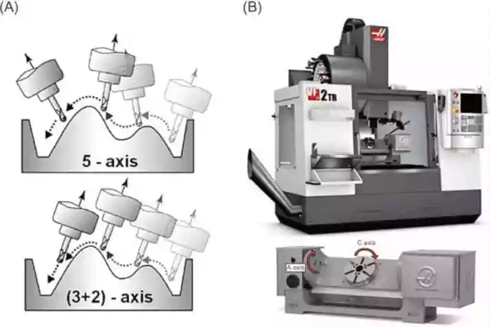
3+2 axis machining and continuous 5-axis machining are both based on five-axis CNC platforms, but they use rotary axes in different ways. The main difference is that 3+2 axis machining uses rotary axes for positioning, while continuous 5-axis machining uses all five axes simultaneously during cutting.
| Comparison | 3+2 Axis Machining | Continuous 5-Axis Machining |
| Axis Movement | Rotary axes position the workpiece or tool to a fixed angle and lock during cutting. Only X, Y, and Z axes move. | X, Y, Z, and rotary axes move simultaneously, allowing continuous tool orientation changes. |
| Rigidity | Higher rigidity due to mechanical locking of rotary axes, making it suitable for heavy cutting and material removal. | Lower rigidity during cutting because rotary axes remain in dynamic motion. |
| Surface Quality | Excellent for angled features and multi-sided parts, but may require multiple setups for complex curved surfaces. | Ideal for complex freeform surfaces with smoother transitions and fewer tool marks. |
| Programming Complexity | Uses simpler coordinate transformation methods such as TWP, with easier programming and post-processing. | Requires advanced functions such as RTCP/TCPM for real-time tool compensation, making programming more complex. |
| Best Applications | Best for parts with multiple angled faces, holes, pockets, and general multi-sided machining. | Best for molds, impellers, turbine blades, and complex curved components. |
In practical production, many manufacturers combine both methods: 3+2 axis machining is used for roughing and semi-finishing to maximize rigidity and efficiency, while continuous 5-axis machining is used for final finishing of complex surfaces.
DFM Guidelines for 3+2 Axis Machining
To maximize efficiency and lower costs, apply these 4 quick DFM rules during design:
- Minimize Indexing Planes: Group angled features (holes, slots) onto as few planes as possible. Less rotation means faster cycle times.
- Ensure Fixture Clearance: Leave a 3mm–5mm grip allowance at the part bottom for elevated vises. This prevents spindle-to-fixture collisions during tilt.
- Optimize Corner Radii: Make internal corner radii 10% to 20% larger than the cutting tool radius to prevent chatter in deep cavities.
- Align Angled Holes: Align the axes of angled holes to be parallel where possible. This lets the machine drill them in a single lock, avoiding extra indexing.
Conclusion
3+2 axis machining is the perfect bridge between simplicity and capability. By using standard 3-axis programming to achieve “one-setup, multi-sided” production, it delivers maximum rigidity and ROI for complex manifolds, housings, and mold components.
At Xtmade, we leverage advanced multi-axis CNC technology to bring these complex designs to life. Our experienced DFM engineering team reviews your files upfront to eliminate interference, optimize machining planes, and reduce setups. Whether you need rapid prototypes or production-grade components, Xtmade makes high-precision manufacturing simple, fast, and highly cost-effective.