How to Design Parts for CNC Machining: Complete DFM Guidelines for Engineers
Designing parts for CNC machining requires more than creating a functional CAD model. The way a part is designed directly affects machining accuracy, production efficiency, surface finish, lead time, and overall manufacturing cost.
Unlike additive manufacturing or injection molding, CNC machining removes material using cutting tools with fixed geometries. Features such as internal corners, wall thickness, hole sizes, threads, pockets, and tolerances must be designed according to machining capabilities to avoid unnecessary complexity and manufacturing issues.
A well-designed CNC part should balance functional requirements, manufacturability, and cost efficiency. By following proper CNC machining design guidelines and applying Design for Manufacturing (DFM) principles, engineers can reduce machining difficulties, improve part quality, and achieve more reliable production results.
This guide covers the essential rules for designing parts for CNC machining, including material selection, wall thickness recommendations, hole and thread design, CNC tolerances, surface finish requirements, technical drawings, and practical DFM tips to help you create production-ready CNC parts.
1.Understand CNC Machining Design Limitations
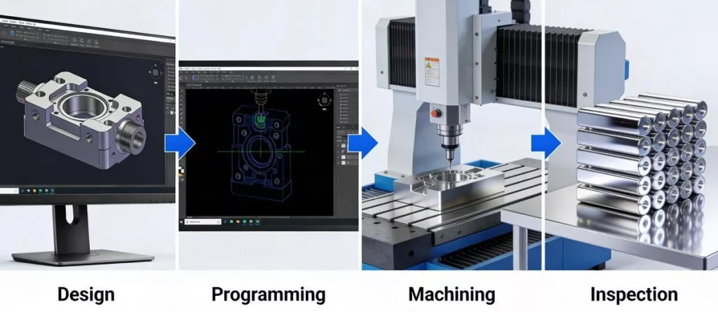
Before designing a part for CNC machining, engineers need to understand the fundamental limitations of the machining process. Unlike 3D printing or molding, CNC machining uses rotating cutting tools to remove material from a solid workpiece. The size, shape, and accessibility of these tools directly influence the achievable part geometry.
A successful CNC part design should consider machining constraints from the beginning, rather than modifying the design after manufacturing issues occur. Understanding these limitations helps prevent common problems such as difficult tool access, excessive machining time, poor surface finish, and increased production costs.
The main factors that affect CNC machining design include:
- Tool geometry and cutting tool size
- Machine axis configuration
- Part orientation and machining setups
- Internal corner requirements
- Feature accessibility
- Material removal requirements
1.1 Consider CNC Tool Geometry and Cutting Limitations
CNC machines create parts by moving rotating cutting tools along programmed paths. Since most CNC cutting tools have a cylindrical shape, they cannot produce perfectly sharp internal corners or infinitely small features.
For example, when machining an internal pocket, the tool radius creates a natural corner radius. Attempting to design sharp 90-degree internal corners may require special tools, additional processes, or alternative manufacturing methods.
CNC design recommendations:
- Add internal corner radii whenever possible
- Match corner radii with standard end mill sizes
- Avoid extremely small features that require custom tooling
- Consider tool diameter when designing narrow slots and pockets
A larger internal radius can improve:
- Tool strength and lifespan
- Cutting efficiency
- Surface quality
- Overall machining cost
Design Example:
Poor CNC design:
- Sharp internal corners
- Deep narrow pockets
- Small features requiring special tools
Improved CNC design:
- Rounded internal corners
- Standard tool-compatible geometry
- Accessible machining features
1.2 Design Parts for Proper Tool Access
Tool accessibility is one of the most important considerations in design for CNC machining. Every machined feature must allow the cutting tool to approach the surface without interference from other part geometry.
Poor tool access can lead to:
- Additional machining setups
- Longer production time
- Reduced accuracy
- Higher manufacturing costs
When designing CNC parts, consider:
- Can the tool reach the feature directly?
- Is the feature visible from the machining direction?
- Does the part require multiple setups?
- Can the geometry be simplified?
For complex components, using 4-axis or 5-axis CNC machining can improve access to angled surfaces and reduce the number of setups. However, optimizing the design for standard 3-axis machining whenever possible usually provides better cost efficiency.
1.3 Consider Machine Setup and Part Orientation
Every time a CNC machine needs to reposition or hold a part in a new orientation, additional setup time is required. Parts designed with fewer setups are generally faster and more economical to manufacture.
Good CNC design practices include:
- Keeping important features on the same machining side
- Avoiding unnecessary complex orientations
- Designing reference surfaces for stable fixturing
- Reducing the number of required operations
For production CNC machining, reducing setups helps improve:
- Dimensional consistency
- Repeatability
- Machining efficiency
- Production cost
By considering tool limitations, accessibility, and machining setups during the design stage, engineers can create parts that are easier to manufacture, more cost-effective, and better suited for precision CNC production.
2. Choose the Right Material Before CNC Part Design
Material selection is a critical step in CNC machining design. The material you choose affects machining difficulty, part strength, dimensional accuracy, surface finish, production time, and overall cost.
A well-designed CNC part should not only meet functional requirements but also match the machining characteristics of the selected material. Choosing the wrong material can lead to higher tool wear, longer machining cycles, poor surface quality, or difficulty achieving tight tolerances.
2.1 Common CNC Machining Materials
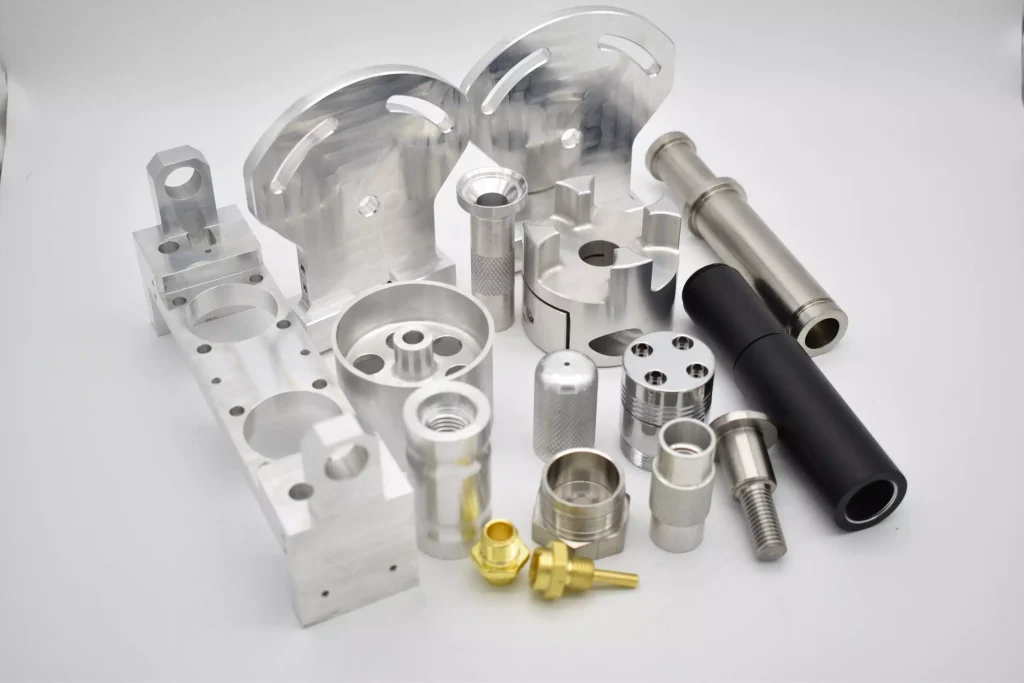
CNC machining supports a wide range of metals and plastics. The most common materials include aluminum, stainless steel, titanium, brass, copper, and engineering plastics.
| Material | Advantages | Common Applications |
| Aluminum 6061/7075 | Excellent machinability, lightweight, high strength-to-weight ratio | Aerospace parts, housings, brackets |
| Stainless Steel 304/316 | High corrosion resistance and durability | Medical, food processing, industrial components |
| Titanium | High strength, lightweight, excellent corrosion resistance | Aerospace, medical applications |
| Brass/Copper | Good electrical conductivity and wear resistance | Connectors, precision components |
| PEEK/Nylon/POM | Lightweight, chemical resistance, electrical insulation | Plastic components, prototypes |
2.2 How Material Choice Affects CNC Design
Different materials require different design considerations. Material properties influence feature sizes, wall thickness, tolerances, and finishing requirements.
For example, aluminum is easier to machine and allows higher cutting speeds, making it suitable for complex geometries and thin-wall components. In comparison, harder materials such as stainless steel and titanium require more robust designs to reduce vibration and prevent tool deflection.
Material selection also affects:
- Wall thickness: Harder materials usually require stronger geometries to avoid deformation.
- Tolerances: Materials with high thermal expansion may require additional machining considerations.
- Surface finish: Material hardness and cutting behavior influence achievable surface quality.
2.3 Design Tip: Balance Performance and Manufacturability
The lowest-cost material is not always the most economical choice. A material that is difficult to machine may increase machining time, tooling costs, and finishing requirements.
When selecting materials for CNC part design, engineers should consider:
- Required mechanical properties
- Operating environment
- Weight requirements
- Machining complexity
- Surface finish expectations
By selecting the right material early in the design process, engineers can create CNC parts that are easier to manufacture, more reliable, and more cost-effective.
3. CNC Machining Design Guidelines for Common Features
The geometry of a CNC machined part has a direct impact on manufacturability, machining time, accuracy, and production cost. Features such as walls, holes, threads, pockets, and internal corners must be designed according to CNC machining capabilities to ensure reliable production.
Unlike manufacturing processes that can create complex shapes directly, CNC machining relies on rotating cutting tools with specific sizes and cutting directions. Poorly designed features may require additional setups, special tooling, or secondary operations, increasing both lead time and cost.
Following proper CNC machining design guidelines allows engineers to create parts that are easier to machine while maintaining the required functionality and performance.
3.1 Design Appropriate Wall Thickness for CNC Parts
Wall thickness is one of the most important factors in CNC machining design. If a wall is designed too thin, cutting forces and tool pressure can cause vibration, deformation, or even part failure during machining.
Unlike molded or printed parts, CNC machining requires the cutting tool to physically remove material from the workpiece. Thin sections have less structural support and are more sensitive to machining forces, especially when using harder materials or deep cavity designs.
Recommended CNC Wall Thickness Guidelines
The minimum wall thickness depends on the material, part size, machining method, and required accuracy.
| Material | Recommended Minimum Wall Thickness |
| Aluminum | 0.8 mm or greater |
| Steel / Stainless Steel | 1.0 mm or greater |
| Plastics | 1.5 mm or greater |
For most CNC machined parts, thicker walls improve rigidity and dimensional stability. However, increasing wall thickness unnecessarily can increase material usage and machining time.
How to Avoid Thin Wall Machining Problems
When designing thin-wall CNC parts:
- Avoid extremely tall and thin features
- Keep wall height proportional to thickness
- Use ribs or support structures when possible
- Reduce cutting depth for delicate areas
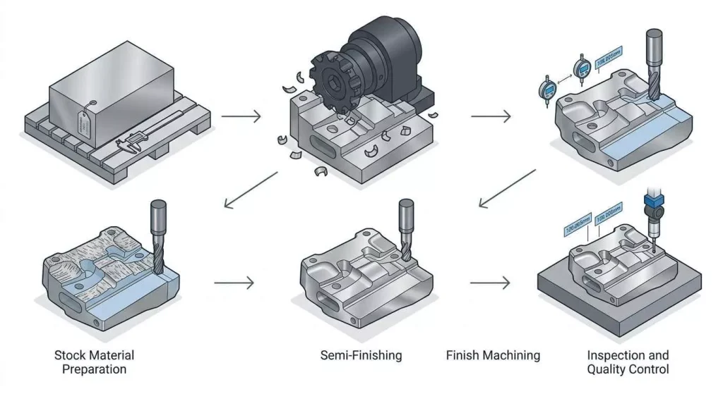
For precision components, engineers should also consider machining sequence and tool selection. Roughing operations may need to remove material gradually before finishing passes are applied to maintain accuracy.
3.2 Optimize Hole Design for CNC Machining
Holes are among the most common features in CNC machined components and are used for fastening, alignment, assembly, and weight reduction. Although holes are simple geometric features, their size, depth, and tolerance requirements significantly affect machining processes.
Whenever possible, designers should use standard drill sizes because common tooling improves efficiency and reduces manufacturing costs. Custom hole sizes may require additional tools or operations.
Important considerations for CNC hole design include:
- Use standard hole diameters whenever possible
- Avoid extremely small holes unless necessary
- Limit deep holes to prevent tool deflection
- Specify tight tolerances only for functional holes
Hole depth is another important factor. Deep, narrow holes require longer tools, which are more prone to vibration and bending. For standard drilling operations, keeping the hole depth within approximately four times the diameter helps maintain accuracy and tool stability.
For precision holes requiring tighter control, additional processes such as reaming, boring, or honing may be required.
3.3 Design Threads According to CNC Machining Requirements
Threaded features are commonly used for assembly and fastening in CNC machined parts. Proper thread design ensures reliable connections while avoiding unnecessary machining complexity.
When designing threaded holes, engineers should consider thread size, depth, material strength, and accessibility.
Recommended practices include:
- Use standard thread sizes whenever possible
- Avoid extremely small threads in difficult-to-machine areas
- Provide sufficient thread engagement depth
- Consider material strength when selecting thread size
For example, aluminum parts may require larger thread engagement or threaded inserts when repeated assembly is expected. Hard materials may require different machining strategies to maintain thread quality.
Clear thread specifications on engineering drawings, including thread type, size, depth, and tolerance requirements, help prevent manufacturing errors.
3.4 Add Proper Internal Corner Radii and Fillets
CNC cutting tools are typically cylindrical, which means they naturally create rounded internal corners. Unlike processes such as molding, CNC machining cannot produce perfectly sharp internal 90-degree corners without special tooling or additional operations.
Adding appropriate corner radii improves:
- Tool strength
- Cutting efficiency
- Surface quality
- Machining reliability
A larger internal radius allows the cutting tool to remove material more efficiently and reduces sudden changes in cutting direction.
Poor design:
- Sharp internal corners
- Small radii requiring special tools
Better design:
- Rounded internal corners
- Radii matched with standard end mills
For most CNC machined parts, designing internal corners based on available tooling is a more cost-effective approach.
3.5 Optimize Pocket and Cavity Design
Pockets and cavities are frequently used to reduce weight, create mounting areas, or achieve complex part geometries. However, deep and narrow pockets can create machining challenges because of limited tool access and increased cutting vibration.
When designing CNC pockets:
- Avoid excessive depth-to-width ratios
- Use larger corner radii
- Provide enough space for tool movement
- Consider chip removal requirements
Deep pockets often require longer cutting tools, which can reduce rigidity and affect surface finish. If a deep cavity is necessary, designers should consider whether multi-axis CNC machining or additional setups are required.
3.6 Avoid Unnecessary Undercuts
Undercuts are features that cannot be reached by standard cutting tools from normal machining directions. Examples include T-slots, dovetail grooves, and hidden internal features.
While CNC machining can produce undercuts, they often require specialized tools or additional setups, which increases manufacturing complexity.
To improve manufacturability:
- Avoid unnecessary undercut features
- Use standard tooling where possible
- Consider alternative geometries that provide similar functionality
If an undercut is required, engineers should communicate the exact requirements in the CAD model and technical drawings to ensure the correct machining approach is selected.
By considering wall thickness, holes, threads, corner radii, pockets, and undercuts during the design stage, engineers can significantly improve the manufacturability of CNC parts. These principles form the foundation of Design for CNC Machining (DFM) and help achieve better quality, shorter lead times, and lower production costs.
4. Design for CNC Machining Accuracy and Tolerances
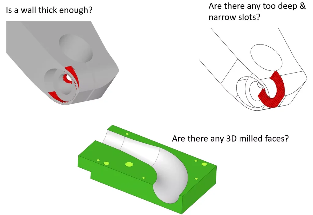
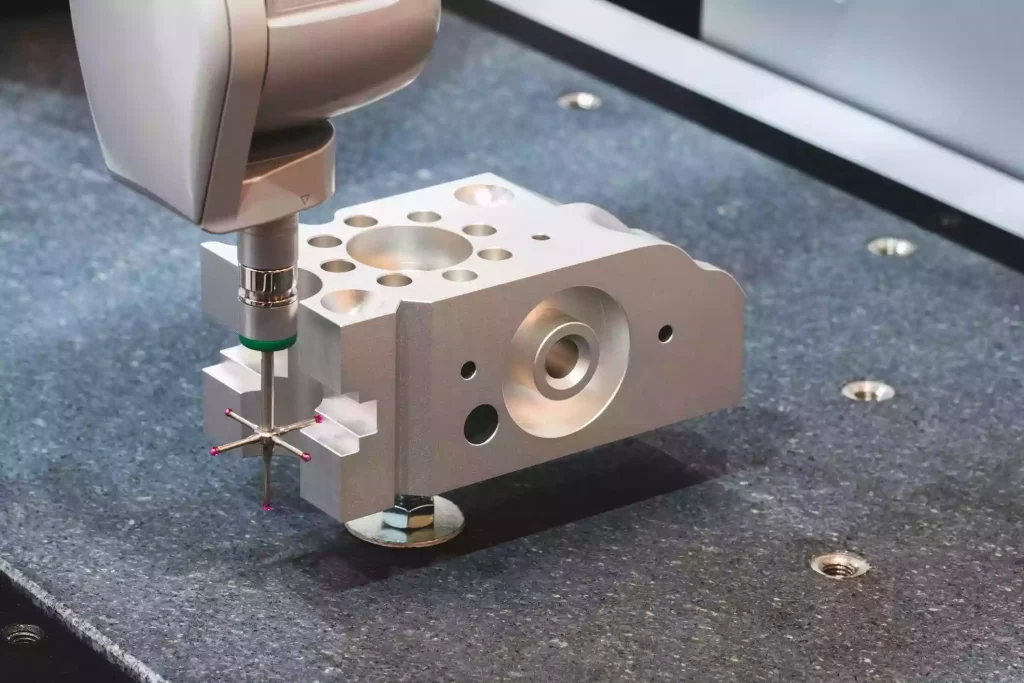
Accuracy and tolerance requirements play an important role in CNC part design. Although modern CNC machines can achieve very high precision, not every feature requires the same level of accuracy. Applying unnecessarily tight tolerances throughout a part often increases machining time, inspection requirements, and production costs without improving the actual function of the component.
When designing parts for CNC machining, engineers should first identify which dimensions are critical to assembly or performance. Features such as bearing bores, mating surfaces, alignment holes, and sealing areas may require tighter control, while non-functional dimensions can usually follow standard machining tolerances.
4.1 Understanding CNC Machining Tolerances
CNC machining tolerance refers to the allowable variation between the designed dimension and the final manufactured dimension. The achievable tolerance depends on factors such as machine capability, material properties, part geometry, machining strategy, and inspection methods.
For most standard CNC machining applications, tolerances are typically within ±0.01 mm to ±0.05 mm. Precision machining processes can achieve tighter tolerances when the design, equipment, and quality control processes are optimized.
However, achieving tighter tolerances requires more than just selecting a high-precision CNC machine. The part itself must be designed for machining stability. Thin walls, large unsupported surfaces, deep cavities, and complex geometries can introduce vibration or deformation, making it more difficult to maintain accuracy.
4.2 Avoid Over-Specifying Tolerances
One of the most common CNC design mistakes is applying tight tolerances to every dimension on a drawing. While this may appear to improve quality, it often increases manufacturing difficulty and cost.
A better approach is to define tolerances based on part function. If a dimension affects assembly, movement, sealing, or alignment, tighter control may be necessary. For cosmetic or non-critical features, standard tolerances are usually sufficient.
4.3 Using GD&T for Precision CNC Parts
For complex components, traditional dimensional tolerances may not fully describe the design intent. GD&T (Geometric Dimensioning and Tolerancing) provides a clearer method for controlling the form, orientation, and position of features.
For example, a hole may have the correct diameter but still be incorrectly positioned relative to other features. A position tolerance ensures that the hole location remains within the required functional range.
Using GD&T correctly helps engineers communicate requirements more clearly and reduces potential manufacturing misunderstandings.
4.4 Design for Better Accuracy
Good CNC accuracy starts during the design stage. Parts with sufficient rigidity, reasonable wall thickness, accessible features, and stable machining setups are easier to manufacture within tight tolerances.
By balancing precision requirements with manufacturability, engineers can create CNC parts that achieve the necessary performance while avoiding unnecessary production costs.
5. Consider Surface Finish Requirements in CNC Design
Surface finish is an important consideration when designing parts for CNC machining. The machined surface quality affects not only the appearance of a component but also its functionality, friction performance, sealing capability, wear resistance, and compatibility with other parts.
A common mistake in CNC part design is specifying a surface finish requirement without considering how the machining process will achieve it. Surface roughness is influenced by factors such as material type, cutting parameters, tool selection, machining direction, and post-processing methods.
A well-designed CNC part should define surface finish requirements based on the actual application rather than selecting the smoothest possible finish for every surface.
5.1 Understanding CNC Surface Finish
Surface finish describes the texture and roughness of a machined surface. It is commonly measured using Ra (average surface roughness), where a lower Ra value indicates a smoother surface.
For CNC machined parts, typical surface finishes include:
| Surface Finish | Typical Application |
| As-machined finish | General mechanical components and prototypes |
| Fine machined finish | Precision mating surfaces and functional components |
| Polished finish | Appearance-critical parts and optical applications |
| Bead blasted finish | Uniform matte appearance and improved surface texture |
The required surface finish should be determined by the part’s function. For example, a mounting surface may require better flatness and finish control, while a hidden internal feature may only need standard machining quality.
5.2 Design Surfaces Based on Function
Not every surface on a CNC part needs the same finish requirement. Applying a high surface finish specification to the entire component can increase machining time and cost.
Engineers should identify functional surfaces that require additional attention, such as:
- Assembly contact areas
- Sealing surfaces
- Sliding or rotating interfaces
- Cosmetic exterior surfaces
Other non-critical areas can typically maintain standard CNC machining finishes.
This approach helps manufacturers focus resources where they provide the most value while keeping production efficient.
5.3 Consider Material and Machining Process Effects
Different materials respond differently during machining. Softer materials such as aluminum can often achieve excellent surface finishes with proper tooling and cutting parameters, while harder materials such as stainless steel or titanium may require additional machining strategies.
The final surface quality can also be affected by:
- Tool sharpness and wear
- Cutting speed and feed rate
- Tool path strategy
- Part rigidity
- Coolant conditions
For precision CNC components, surface finish requirements should be considered together with dimensional tolerances. A part with tight dimensional control but poor surface quality may still fail to meet functional requirements.
5.4 CNC Surface Finish and Post-Processing Options
Many CNC machined parts require additional surface treatments after machining to improve appearance, durability, or corrosion resistance.
Common post-processing options include:
- Anodizing for aluminum parts
- Passivation for stainless steel components
- Bead blasting for uniform texture
- Polishing for high-appearance applications
- Coating treatments for additional protection
When designing CNC parts, engineers should consider whether the required surface condition can be achieved through machining alone or whether secondary finishing operations are necessary.
Proper surface finish planning is an essential part of design for CNC machining. By specifying realistic finish requirements and considering manufacturing capabilities early in the design process, engineers can achieve the right balance between part performance, appearance, and production cost.
6. Prepare Complete CNC Technical Drawings
A complete technical drawing is an important part of CNC machining design. While a 3D CAD model defines the shape and geometry of a part, the engineering drawing provides additional manufacturing requirements, including dimensions, tolerances, materials, and finishing specifications.
A clear CNC drawing ensures that manufacturers understand the design intent and produce parts according to functional requirements. Missing or unclear information can lead to machining errors, inspection issues, and unnecessary production revisions.
6.1 Include Key Manufacturing Requirements
A CNC machining drawing should include all critical information needed for manufacturing and inspection. This includes part dimensions, tolerance requirements, material specifications, surface finish, thread details, and any required secondary processes.
Dimensions that affect assembly, fit, or performance should be clearly identified with appropriate tolerances. Avoid applying tight tolerances to every feature, as unnecessary precision can increase machining difficulty and cost.
6.2 Use GD&T to Define Critical Features
For precision CNC parts, standard dimensions may not fully describe the relationship between different features. GD&T (Geometric Dimensioning and Tolerancing) provides a clearer method for controlling feature location, orientation, and form.
Using GD&T helps define requirements such as hole position, flatness, and alignment, ensuring that manufacturers and inspectors have a consistent understanding of critical design requirements.
6.3 Specify Material and Surface Finish Requirements
Material selection and surface treatment requirements should be clearly stated on the drawing. Different materials require different machining strategies, while processes such as anodizing, passivation, or coating may affect final dimensions.
Including these details in advance helps manufacturers select suitable machining processes and avoid issues during production.
6.4 Define Threads and Complex Features Clearly
Features such as threaded holes, pockets, slots, and precision openings should include complete specifications rather than relying only on the CAD model.
For threaded features, the drawing should define the thread standard, size, depth, and fit requirements. Clear feature descriptions reduce interpretation errors and improve manufacturing consistency.
6.5 Create Drawings with Manufacturing in Mind
A good CNC drawing should communicate necessary requirements without unnecessary complexity. Overly strict tolerances, unclear dimensions, or missing specifications can increase production difficulty.
By creating accurate and practical technical drawings, engineers can improve communication, reduce manufacturing risks, and ensure reliable CNC machining results.
7. Reduce CNC Machining Cost Through Better Design
CNC machining cost is closely related to part design. Factors such as unnecessary complexity, excessive machining operations, and unrealistic precision requirements can increase production time and manufacturing expenses. By applying Design for CNC Machining (DFM) principles early in the design process, engineers can create CNC parts that are easier to manufacture and more cost-effective.
A practical CNC machining design should focus on achieving the required function with efficient manufacturing methods. Complex geometries, difficult tool access, and unnecessary secondary operations can increase machining difficulty. Simplifying the design while maintaining performance is one of the most effective ways to reduce CNC machining costs.
When optimizing a part design, engineers should consider:
- Reducing unnecessary deep pockets and complex undercuts
- Minimizing the number of machining setups
- Avoiding excessive tight tolerances on non-critical features
- Using standard hole sizes, threads, and corner radii
- Selecting designs that allow standard CNC tooling
Tolerance requirements also have a significant impact on cost. Although precision CNC machining can achieve high accuracy, tighter CNC machining tolerances require additional process control and inspection. Engineers should only specify strict tolerances for functional areas such as mating surfaces, alignment features, and critical holes.
Material usage is another important consideration. Designs that require excessive material removal or complicated machining paths often increase machining time and tool wear. Optimizing part geometry and selecting appropriate material sizes can improve production efficiency while maintaining the required strength and performance.
A cost-effective CNC part design is not about reducing quality or eliminating necessary features. Instead, it focuses on creating parts that are functional, manufacturable, and optimized for efficient CNC production.
8. CNC Machining Design Checklist Before Manufacturing
Before starting CNC production, a final design review helps identify potential manufacturing issues and reduce unnecessary modifications. A complete CNC machining design should consider both the functional requirements of the part and the limitations of the manufacturing process.
By applying Design for CNC Machining (DFM) principles before production, engineers can improve manufacturability, reduce machining difficulties, and ensure that CAD models and technical drawings are ready for manufacturing.
Before submitting a part for CNC machining, review the following key points:
- The part geometry is suitable for CNC machining and allows proper tool access
- Wall thickness, internal corner radii, and feature sizes are manufacturable
- Hole, thread, and pocket designs follow CNC machining guidelines
- Critical dimensions have appropriate CNC machining tolerances
- Material and surface finish requirements are clearly defined
- Technical drawings include necessary manufacturing information
A proper CNC design review helps prevent production delays, reduce redesign costs, and improve machining efficiency. Following these CNC machining design guidelines allows engineers to create parts that are accurate, reliable, and ready for production.
Designing for On-Demand Manufacturing
A well-designed part is the foundation of successful CNC machining, but selecting the right manufacturing partner is equally important. An experienced CNC machining supplier can help transform your design into high-quality finished parts while improving manufacturability, production efficiency, and overall reliability.
Xtmade provides comprehensive CNC machining services for rapid prototyping, low-volume production, and custom part manufacturing. With advanced machining capabilities and engineering expertise, we help customers optimize their CNC part designs, select suitable materials, and produce precision components that meet specific application requirements.
From initial design review to final production, Xtmade works closely with customers to evaluate machining feasibility, improve manufacturing processes, and ensure consistent quality.
Upload your CAD files, share your material and project requirements, and Xtmade’s engineering team will provide professional support to turn your CNC machining designs into reliable production-ready parts.