Precision Machining of New Energy Vehicle Motor Shafts: Processes and Case Studies
The drive motor is a key component of a new energy vehicle’s powertrain. As an important part of the motor assembly, the motor shaft supports the rotor core, maintains its position, and transmits torque during operation. Its dimensional accuracy, geometric tolerances, and surface quality directly affect assembly precision, rotational stability, and operating reliability.
Compared with conventional transmission shafts, new energy vehicle motor shafts often feature more complex geometries, including external splines, keyways, deep holes, stepped diameters, and precision bearing journals. Depending on the design, these features may require multiple machining operations to achieve the required dimensions and positional accuracy.
Precision machining of new energy vehicle motor shafts involves a combination of CNC turning, drilling, spline machining, keyway milling, and grinding. This article examines three representative shaft configurations, explains their machining requirements, and discusses the key quality controls involved in manufacturing these components.
Structural Characteristics of New Energy Vehicle Motor Shafts
Motor shaft structures vary according to motor design, assembly requirements, and torque transmission methods. From a manufacturing perspective, hollow and solid shafts present different challenges in terms of rigidity, machining access, and dimensional control.
Hollow Motor Shafts for Nova Energia
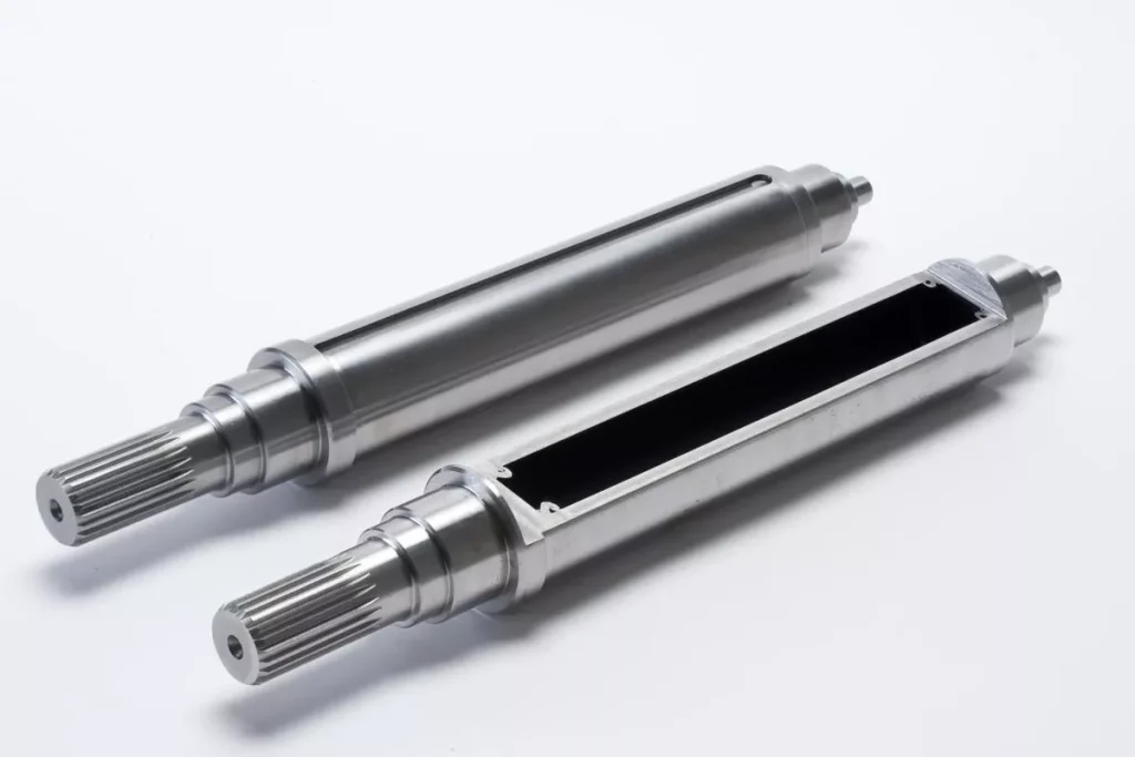
Hollow motor shafts are used in applications where reducing rotating mass is important. Their internal bores may also accommodate specific structural or functional requirements.
The reduced wall thickness makes these shafts more sensitive to clamping pressure and cutting forces. Excessive force can cause deformation, while unsuitable machining conditions may result in vibration and dimensional variation. Internal bore accuracy is another important consideration, particularly when the bore axis must maintain a defined relationship with the external shaft surfaces.
Solid Motor Shafts for Nova Energia
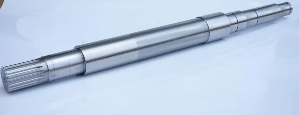
Solid motor shafts have a continuous material cross-section and generally offer greater rigidity during machining. Typical features include stepped diameters, bearing journals, external splines, and keyways.
Although solid shafts are generally easier to support than hollow designs, their functional features still require accurate positioning relative to one another. In particular, the relationship between bearing journals, spline teeth, and keyways affects assembly alignment and torque transmission. Maintaining consistent machining references is therefore essential throughout production.
Main Machining Processes for Motor Shafts
The machining route depends on the shaft drawing, material, blank condition, heat treatment, tolerance requirements, and production volume. The following processes are commonly used in motor shaft manufacturing.
Torneamento CNC
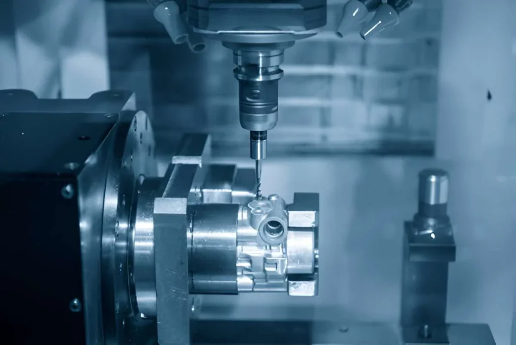
Torneamento CNC produces the main external features of motor shafts, including stepped diameters, bearing journals, shoulders, and end faces. For long or hollow shafts, workholding rigidity and cutting force control are particularly important to prevent deflection and dimensional variation. Rough and finish turning are generally arranged separately, with appropriate machining allowance reserved for subsequent grinding when required.
Drilling and Deep-Hole Machining
Drilling and deep-hole machining are used to produce internal bores in hollow motor shafts. As hole depth increases, chip evacuation, tool guidance, and coolant delivery become more challenging. Gun drilling or BTA drilling may be selected according to bore dimensions and accuracy requirements. Key considerations include bore diameter, straightness, surface finish, and the positional relationship between the internal bore and external shaft surfaces.
Spline Machining
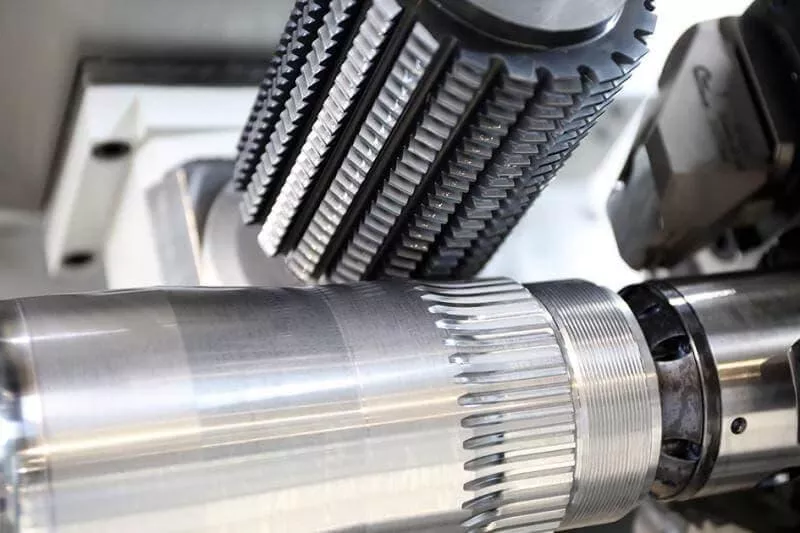
External splines transmit torque between the motor shaft and connected components. Depending on the spline profile, tooth count, accuracy requirements, and production volume, suitable methods may include spline hobbing, shaping, or milling. Tooth thickness, profile accuracy, and the spline’s alignment with the shaft datum are important factors affecting the final fit and transmission performance.
Keyway Milling
Keyways provide a mechanical connection between the shaft and mating components through a key. CNC milling is commonly used to produce the required slot width, depth, length, and position. For shafts with two or more keyways, angular indexing must also be controlled to ensure the correct orientation between slots and other functional features.
Knurling and Spline Rolling
Knurling uses dedicated rollers to form surface patterns through plastic deformation, typically for grip or specific surface engagement requirements. Spline rolling is a different process in which shaped dies form spline teeth through controlled material displacement. It can be suitable for certain materials and production volumes, depending on the spline geometry and dimensional requirements. Neither process is required for every motor shaft design.
CNC Cylindrical Grinding
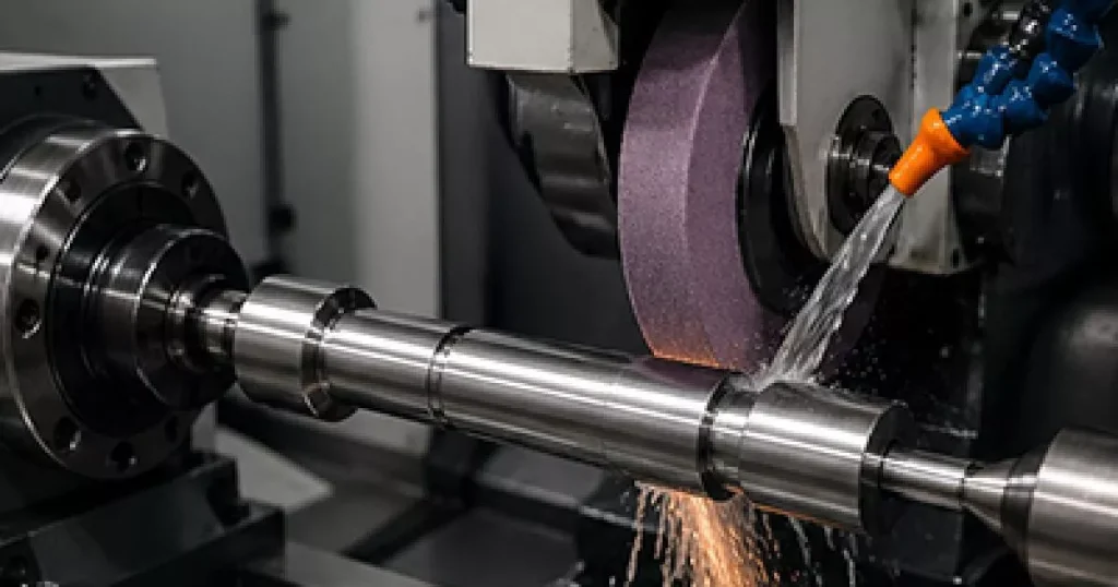
CNC cylindrical grinding is used to finish critical external diameters, particularly bearing journals and precision fitting surfaces. It helps achieve tighter dimensional tolerances, improved roundness, and better surface finishes than turning alone may provide. Grinding parameters, wheel condition, and coolant control must be managed to avoid thermal damage, grinding burns, and surface defects.
Machining Analysis of Three Motor Shaft Configurations
The following three configurations represent common combinations of hollow or solid shaft structures and external transmission features. Their machining routes should be finalized according to the actual drawings, materials, blank conditions, heat treatment, and tolerance requirements.
Hollow Motor Shaft with External Splines and an Internal Deep Hole
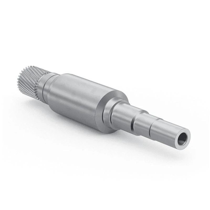
This configuration combines an external spline with a central internal bore. The external spline provides the torque-transmission interface, while the deep hole forms the hollow structure of the shaft.
The main manufacturing challenge is maintaining the positional relationship between the internal bore and external functional surfaces. Deep-hole drilling requires effective chip evacuation and tool guidance to prevent bore deviation. At the same time, the reduced wall thickness makes the shaft more sensitive to clamping forces and cutting deformation.
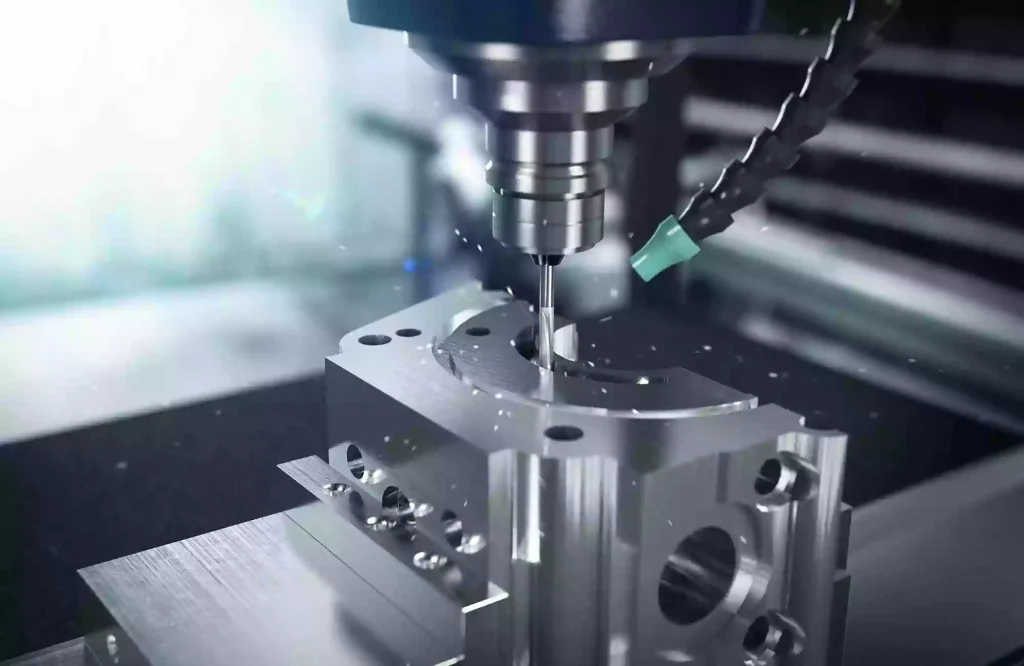
A typical machining plan may involve preparing the blank, machining the internal bore and external reference surfaces, turning the stepped outer diameters, and producing the external spline. The exact sequence should be determined by the drawing and the required datum relationships. Critical external diameters may undergo cylindrical grinding after heat treatment or other intermediate operations.
Inspection should focus on the bore diameter and straightness, external diameter accuracy, spline geometry, and the positional relationship between the bore and external shaft surfaces.
Hollow Motor Shaft with External Splines, a Keyway, and an Internal Deep Hole
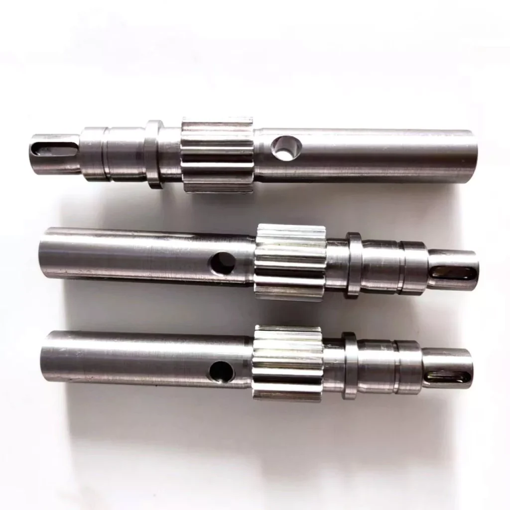
This design combines three important features: a hollow internal structure, an external spline, and a keyway. Compared with the first configuration, the additional keyway introduces another positioning requirement and increases the complexity of the machining setup.
The internal bore must maintain its required geometry without causing excessive variation in wall thickness. The external spline must meet the specified tooth profile and fit requirements, while the keyway must maintain accurate width, depth, length, and angular position.
A typical route may include blank preparation, drilling or deep-hole machining, CNC turning, spline machining, and keyway milling. The order of spline machining and keyway milling depends on the workholding strategy and the datum structure specified in the drawing. If the keyway is machined after the spline, the fixture must provide reliable angular positioning relative to the spline teeth.
Inspection should cover the internal bore, shaft diameters, spline dimensions, and keyway geometry. Particular attention should be given to the angular relationship between the keyway and spline, as well as the alignment of the internal and external features.
Solid Motor Shaft with External Splines and Two Keyways
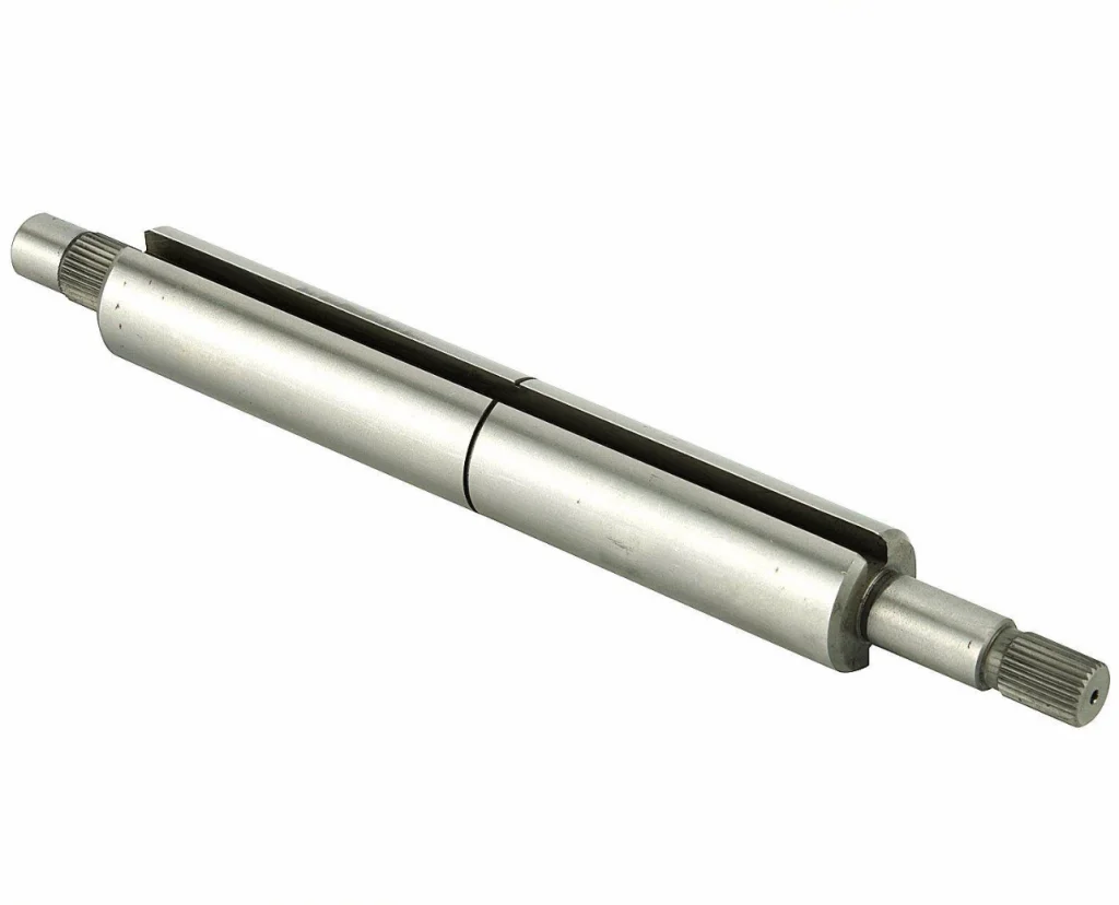
Unlike the previous two configurations, this shaft has a solid structure and does not require internal deep-hole machining. Its main features are the external spline and two keyways, which provide different mechanical connection interfaces.
The solid cross-section generally provides better rigidity during machining. However, the two keyways introduce an additional angular positioning requirement. Both slots must meet their specified dimensions and maintain the correct orientation relative to each other and the shaft datum.
A typical manufacturing route may include CNC turning of the shaft diameters and shoulders, external spline machining, and milling of the two keyways. Depending on the drawing, the keyways may be machined using a dividing fixture, a CNC rotary axis, or another suitable positioning method. Critical bearing journals may require subsequent cylindrical grinding.
Quality inspection should verify the spline profile and fit, keyway width and depth, angular spacing between the two slots, and the runout of functional shaft surfaces. Consistent datum references are important to prevent positioning errors between separate machining setups.
Key Quality Control in Motor Shaft Machining
The quality of a motor shaft depends not only on the accuracy of individual features but also on their geometric relationships. Inspection should therefore be based on the functional dimensions and geometric tolerances specified in the engineering drawing.
Precisão dimensional
Shaft diameters, stepped sections, bearing journals, and internal bores must meet their specified dimensional tolerances. Outside micrometers, bore gauges, and other suitable precision measuring instruments can be used to verify these dimensions.
For precision bearing journals and fitting surfaces, inspection should also consider roundness and cylindricity rather than relying on diameter measurements alone.
Concentricity and Runout
The relationship between the shaft’s functional surfaces is critical to stable rotation and accurate assembly. External diameters, bearing journals, splines, and internal bores may need to maintain defined geometric relationships with the selected datum axis.
Runout measurement can help evaluate the variation of a surface during rotation relative to a reference axis. Concentricity, position, and total runout are different geometric controls, so the inspection method should match the actual drawing requirements rather than treating them as interchangeable terms.
Rugosidade da superfície
Bearing journals and other fitting surfaces often require controlled surface roughness to support proper contact and assembly. Turning and grinding parameters should be selected according to the material, dimensional tolerance, and specified finish.
After grinding, the surfaces should also be checked for burns, chatter marks, scratches, and other defects that may affect service performance.
Spline and Keyway Inspection
Spline inspection should consider the dimensions and geometry that determine the fit with the mating component. Depending on the specified spline standard and tolerance class, inspection may involve spline gauges, dedicated measuring equipment, or profile measurement systems.
Keyway inspection should verify slot width, depth, length, and position. For shafts with multiple keyways, the angular relationship between slots must also be checked.
Inspection and Dimensional Verification
Inspection methods should be selected according to the feature being measured. CMMs can be used to evaluate selected dimensional and geometric relationships, while micrometers, bore gauges, dial indicators, spline gauges, and dedicated measuring equipment are more suitable for certain individual features.
For critical motor shafts, a documented inspection plan helps ensure that important dimensions and functional relationships are verified consistently throughout production.
Selecting the Right Machining Route for Motor Shafts
The three configurations discussed above illustrate why motor shaft manufacturing cannot rely on a single standard machining sequence.
Hollow shafts with deep holes require particular attention to bore accuracy, wall thickness, and workholding deformation. Hollow shafts with both splines and keyways introduce additional angular positioning and feature alignment requirements. Solid shafts eliminate the internal drilling operation but still require accurate control of spline geometry, keyway positions, and functional diameters.
The most suitable machining route should be developed from the part drawing and its functional requirements. Material properties, heat treatment, production quantity, available equipment, and inspection capability must also be considered. A well-planned process helps reduce unnecessary setups, control accumulated errors, and maintain consistent dimensional quality.
Custom Motor Shaft Manufacturing at Xtmade
Xtmade is a custom precision manufacturing company based in Shenzhen, China. We work from customers’ existing engineering drawings, CAD files, samples, and specifications to evaluate manufacturing requirements and develop suitable production processes.
Our manufacturing support covers Maquinação CNC and other processes required for custom components, including drawing review, DFM analysis, process planning, production, and quality inspection. For motor shafts and other precision mechanical parts, we focus on dimensional requirements, feature relationships, and manufacturing consistency throughout the process.
Learn more about Xtmade’s manufacturing capabilities or submit your drawings for a manufacturing review.