How to Set CNC Machining Parameters for Different Materials?
CNC machining parameters directly affect cutting efficiency, surface finish, dimensional accuracy, and tool life. When machining different materials, the same cutting speed, feed rate, and depth of cut can produce very different results. A setting that works well for aluminum may cause excessive heat or tool wear when applied to stainless steel or titanium.
Setting the right CNC machining parameters requires more than choosing values from a chart. Material properties, cutting tool specifications, machine rigidity, part geometry, and machining operations all influence how the process should be configured. Understanding these factors helps manufacturers establish stable cutting conditions and achieve consistent part quality.
What Are CNC Machining Parameters?
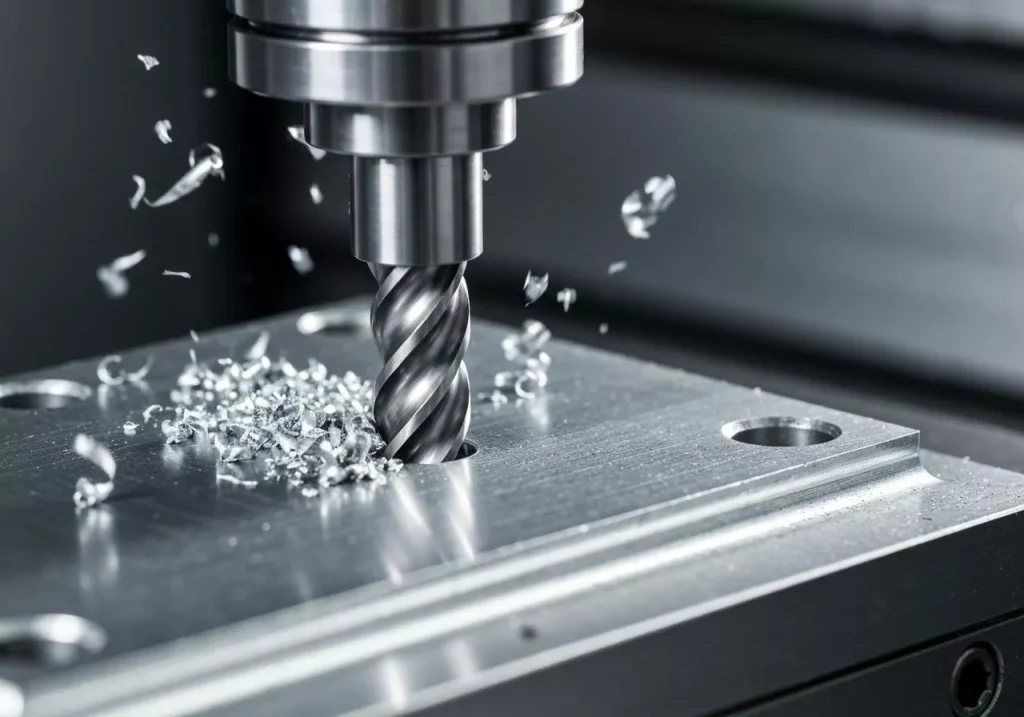
CNC machining parameters are the settings that control how a cutting tool removes material from a workpiece. The main parameters include cutting speed, spindle speed, feed rate, depth of cut, and stepover in milling operations. Coolant selection and tool engagement also influence cutting performance, even though they are not always classified as cutting parameters.
Each setting affects a different aspect of the machining process.
Cutting speed describes how quickly the cutting edge moves relative to the material. It is usually expressed in meters per minute (m/min) or surface feet per minute (SFM). Spindle speed describes how many revolutions the tool or workpiece makes per minute (RPM). Feed rate determines how quickly the tool advances through the material, commonly expressed in millimeters per minute (mm/min).
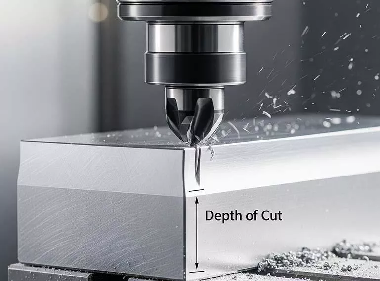
Depth of cut determines how much material is removed in one pass. In milling, this is usually divided into axial depth of cut, which measures engagement along the tool axis, and radial depth of cut, which measures engagement across the tool diameter.
These parameters work together. Increasing spindle speed does not automatically improve productivity, and increasing feed rate does not always shorten machining time without consequences. The goal is to establish a combination that removes material efficiently while controlling cutting forces, temperature, vibration, tool wear, and dimensional variation.
Why Do CNC Machining Parameters Differ by Material?
Different materials respond differently to cutting because they have different hardness, strength, ductility, thermal conductivity, and work-hardening behavior.
Aluminum alloys generally allow relatively high cutting speeds because many grades are easy to cut and transfer heat more effectively than titanium or nickel-based alloys. However, aluminum can adhere to the cutting edge when the tool geometry, coating, or cutting conditions are unsuitable.
Stainless steel presents a different challenge. Some grades generate substantial cutting heat and can work-harden when the cutting edge rubs against the surface instead of cutting cleanly. Excessive speed or insufficient feed may accelerate tool wear or make subsequent passes more difficult.
Titanium alloys and nickel-based superalloys require particularly careful thermal management. These materials can retain heat near the cutting zone, placing greater demands on the cutting edge. Lower cutting speeds, suitable feed rates, controlled tool engagement, and effective coolant delivery are often important.
Plastics introduce another set of considerations. Many plastics are relatively soft, but they can deform under clamping forces, expand with heat, or develop melted surfaces when cutting conditions are unsuitable. Parameters must therefore control both cutting temperature and mechanical deformation.
This is why material-specific parameter selection is essential. The objective is not simply to cut faster, but to maintain a stable process suited to the material and the part.
How to Set Cutting Speed and Spindle Speed
Cutting speed is one of the first parameters to establish because it strongly influences heat generation and tool life. The appropriate range depends on the material grade, cutting tool material, tool coating, operation, and machine capability.
For milling, cutting speed and spindle speed are related through the cutting tool diameter. In metric units, the spindle speed can be calculated as follows:
Spindle speed (RPM) = 1,000 × cutting speed (m/min) ÷ [π × tool diameter (mm)]
For example, if the recommended cutting speed is 200 m/min and the tool diameter is 10 mm, the calculated spindle speed is approximately 6,370 RPM.
This calculation provides a starting point, not a guarantee of the correct setting. The actual spindle speed may need to be reduced if the machine cannot maintain the required power, the tool has excessive overhang, or the part is thin-walled or poorly supported.
Larger tools generally require lower spindle speeds than smaller tools to achieve the same cutting speed. Conversely, a small-diameter tool may require a high RPM to reach the recommended surface speed. Machine spindle limits and tool-holder specifications must always be considered.
For turning, cutting speed is similarly related to spindle speed and workpiece diameter. Constant surface speed control can help maintain the target cutting speed as the tool moves across different diameters, provided the machine and operation support it.

How to Set Feed Rate
Feed rate determines how quickly the tool moves through the material. In milling, it is commonly calculated from the feed per tooth, the number of cutting edges, and spindle speed.
Feed rate (mm/min) = feed per tooth (mm/tooth) × number of teeth × spindle speed (RPM)
For example, a four-flute end mill running at 6,000 RPM with a feed per tooth of 0.03 mm would have a calculated feed rate of 720 mm/min.
The feed per tooth must match the tool diameter, tool geometry, material, and cutting conditions. If the feed is too low, the cutting edge may rub rather than form an effective chip, increasing heat and potentially accelerating wear. If the feed is too high, cutting forces may become excessive, causing chatter, tool deflection, poor surface finish, or tool breakage.
Feed rate also needs to account for the part’s geometry. Thin walls, small internal features, long tool overhangs, and interrupted cuts may require more conservative settings than rigid, open machining features.
For drilling and turning, feed is specified differently depending on the operation. Drilling often uses feed per revolution, while turning commonly specifies feed per revolution as well. The programmed feed rate must reflect the relevant operation rather than applying a milling formula to every process.
How to Set Depth of Cut
Depth of cut determines how much material the tool removes during each pass. Increasing it can reduce the number of passes and shorten cycle time, but it also increases cutting forces and power demand.
A roughing operation is generally intended to remove material efficiently while leaving enough stock for finishing. A finishing operation focuses more on dimensional accuracy and surface quality, often using a smaller depth of cut and a controlled finishing allowance.
The correct depth of cut depends on tool diameter, tool length, cutting-edge geometry, material properties, machine rigidity, workholding, and the amount of tool engagement. A rigid setup may support a larger cut, while a slender tool or thin-walled part may require a much lighter engagement to avoid vibration or deformation.
Material hardness alone does not determine the maximum depth of cut. A hard material may require conservative cutting conditions because of tool wear, while a softer material may still be difficult to machine if the workpiece is flexible or the tool has a long overhang.
For thin-wall CNC machined parts, controlling radial cutting forces can be particularly important. Reducing radial engagement, adjusting the toolpath, and leaving a suitable finishing allowance may help limit wall deflection and improve dimensional consistency.
Recommended Starting Considerations for Different Materials
There is no universal set of CNC machining parameters for an entire material family. The following guidance explains how the initial strategy typically differs. Actual cutting values should come from the cutting tool manufacturer’s recommendations for the specific tool, material grade, and operation.
Aluminiumlegeringen
Aluminum alloys generally support relatively high cutting speeds and productive material removal. Sharp cutting edges, suitable flute geometry, and effective chip evacuation help prevent aluminum from adhering to the tool.
For roughing, the parameters should balance high material removal rates with spindle power, tool engagement, and workpiece rigidity. For finishing, a suitable feed per tooth and sharp tool can help achieve a clean surface without excessive burr formation.
Coolant or appropriate lubrication may be useful depending on the alloy, tool, operation, and required surface quality. Some applications can use air blast or other chip-evacuation strategies, but the choice should be based on the machining conditions rather than a blanket rule.
Roestvrij staal
Stainless steel generally requires more careful control of heat and tool engagement than many aluminum alloys. The appropriate cutting speed varies considerably by grade, including the differences between austenitic, martensitic, and precipitation-hardening stainless steels.
Avoid allowing the cutting edge to rub repeatedly against the material, particularly when the grade is prone to work hardening. Feed, cutting speed, tool geometry, and coolant delivery should be coordinated to maintain a consistent cut.
Stable workholding is also important. Chatter and excessive tool deflection can shorten tool life and damage the surface finish. The selected parameters should reflect the exact stainless steel grade and whether the operation is roughing, finishing, drilling, or turning.
Carbon and Alloy Steel
Carbon and alloy steels cover a broad range of hardness and machinability. A relatively soft, free-machining grade can support different cutting conditions from a hardened alloy steel used for wear-resistant components.
The material’s grade and heat-treated condition should be confirmed before selecting parameters. Cutting speed and feed should then be matched to the tool material and coating. Harder materials may require lower cutting speeds and specialized tooling, while stable setups and appropriate chip control remain important across the range.
For finishing operations, consistency matters as much as nominal speed. Tool wear, thermal variation, and deflection can affect final dimensions, particularly when machining shafts, bores, and precision mating surfaces.
Titaniumlegeringen
Titanium alloys often require lower cutting speeds and careful control of tool engagement because heat can concentrate near the cutting edge. The cutting tool must withstand the resulting thermal and mechanical stresses.
Use parameters recommended for the exact titanium grade and tool system. Maintain a stable cut, avoid unnecessary rubbing, and ensure that coolant reaches the cutting zone when wet machining is specified. Toolpath strategy and engagement control can be just as important as spindle speed.
Thin walls and slender features need particular attention because cutting forces can cause deflection. Reducing engagement or adjusting the machining sequence may improve stability without relying solely on lower feed rates.
Nickel-Based Superalloys
Nickel-based alloys such as Inconel are commonly used in applications that demand high-temperature strength and corrosion resistance. Their properties can make them difficult to machine, especially when the cutting edge experiences high temperatures and repeated mechanical loading.
Cutting speeds are often conservative compared with those used for aluminum, and tooling must be selected for the alloy and operation. Maintaining consistent tool engagement is important because interrupted or unstable cutting can increase tool damage.
Coolant delivery, toolpath planning, machine rigidity, and tool replacement criteria should be established as part of the process. A parameter set that works for one nickel-based alloy should not automatically be transferred to another grade or heat-treated condition.
Copper and Copper Alloys
Copper’s high thermal conductivity and relatively soft behavior can influence chip formation and surface finish. Some copper grades are easy to machine, while others can be gummy or prone to burr formation.
Sharp tools and suitable geometry help reduce smearing and maintain clean edges. Cutting speed and feed should be selected according to the specific copper alloy, tool design, and feature geometry. Because copper alloys vary substantially, recommendations for brass should not automatically be applied to pure copper or other copper grades.
Technische kunststoffen
Engineering plastics require parameter settings that control heat and prevent deformation. Excessive cutting heat may soften or melt the material, while high clamping forces can distort the workpiece.
Use sharp tools and suitable chip-clearance geometry. Feed and speed should be selected for the specific polymer, because POM, PEEK, nylon, PTFE, and other plastics differ in stiffness, thermal behavior, and chip formation. Nylon may also absorb moisture, which can affect dimensions, while PTFE is comparatively soft and can deform under load.
Workholding and inspection conditions matter as well. A plastic part may change dimensions as it cools or returns to equilibrium after machining, so the inspection procedure should account for the material’s behavior.
How to Fine-Tune CNC Machining Parameters
Manufacturer recommendations provide a starting point, but the final settings should be validated under actual machining conditions.
Begin with the confirmed material grade and the cutting tool manufacturer’s recommended ranges for the operation. Check the machine’s spindle speed and power limits, tool-holder specifications, tool overhang, and workholding rigidity before running the program.
During initial machining, observe chip formation, cutting sound, vibration, surface finish, and tool condition. These signs help identify whether the process is stable. Excessive heat, unexpected tool wear, poor chip evacuation, or chatter may indicate that one or more parameters need adjustment.
Change parameters systematically rather than modifying cutting speed, feed, and depth of cut simultaneously. This makes it easier to determine which adjustment improves the result. Where dimensional accuracy is critical, inspect the part after the process has reached a stable condition and account for any temperature-related variation.
The objective is to establish a repeatable process, not simply to find the highest speed or feed that the machine can achieve.
Common Mistakes When Setting CNC Machining Parameters
One common mistake is applying the same parameters to materials that only appear similar. Two stainless steel grades, for example, may behave differently because of their composition, hardness, or heat treatment. Material identification should be confirmed before machining begins.
Another mistake is increasing spindle speed to improve productivity without checking tool limits, heat generation, or machine capability. Higher speed can increase output in suitable conditions, but it can also shorten tool life or cause thermal problems.
Using an excessively low feed rate can be just as problematic as feeding too aggressively. If the cutting edge rubs instead of cutting effectively, heat may build up and some materials may work-harden. Conversely, excessive feed can increase cutting forces and compromise surface quality or tool life.
Finally, treating coolant as a universal solution can lead to poor results. Some operations benefit from flood coolant, high-pressure coolant, minimum-quantity lubrication, or air blast, while other setups have different requirements. The choice should match the material, tool, operation, and machine manufacturer’s guidance.
How Xtmade Approaches CNC Machining Parameter Selection
Xtmade manufactures custom CNC machined parts based on customer-provided drawings, CAD files, samples, and specifications. Machining parameters are selected according to the specified material, part geometry, tolerance requirements, surface finish, and production operation.
During process planning, cutting conditions must be matched to the material grade and cutting tool, while machine capability, workholding, tool access, and chip evacuation are also considered. Thin walls, deep cavities, small features, and tight-tolerance interfaces may require a different strategy from open, rigid features.
The goal is to establish stable, repeatable machining conditions that meet the required dimensions and surface quality while balancing cycle time, tool life, and production consistency.
Conclusie
CNC machining parameters must be matched to the material, cutting tool, machine, and geometry of the part. Aluminum may support higher cutting speeds, while stainless steel, titanium, and nickel-based alloys often require more careful control of heat, tool engagement, and tool wear. Engineering plastics introduce additional concerns related to heat, deformation, and dimensional stability.
Xtmade manufactures custom parts according to customer-provided drawings and specifications. By considering material grade, machining operations, part geometry, and quality requirements together, we establish machining strategies intended to achieve consistent dimensions, suitable surface finishes, and stable production results.