How Does Material Ductility Affect CNC Machining?
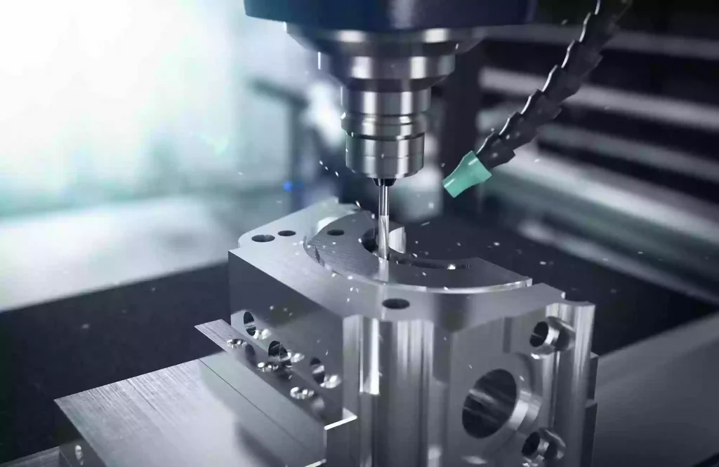
When a CNC cutting tool removes material from a workpiece, the material does not simply snap off the instant the tool makes contact; instead, it undergoes deformation first. Depending on the material, this deformation can result in continuous chips, discontinuous chips, or fine fragments. Some materials stretch and bend around the cutting edge before separating, making chip formation more difficult to control. Ductility is a key material property that explains these differences.
Ductility refers to a material’s ability to undergo plastic deformation before fracturing. Highly ductile materials can withstand significant permanent deformation before breaking, whereas materials with low ductility typically fracture after minimal plastic deformation under similar loading conditions.
In CNC machining, this difference influences how material separates from the workpiece, chip formation, burr generation, and the quality of the machined surface. Highly ductile materials may produce long, continuous chips or deform around the cutting edge prior to separation. Depending on the material and cutting conditions, they may also cause built-up edge (BUE) on the tool or leave burrs along the edges of the machined area.
High ductility does not necessarily mean a material is difficult to machine. Materials such as aluminum, copper, brass, stainless steel, and engineering plastics each exhibit unique combinations of ductility, strength, hardness, and other properties; their actual machining performance depends on more than just ductility alone. Understanding how ductility affects CNC machining helps engineers and manufacturing teams select the right tools, control chip formation, minimize burrs, and achieve consistent surface quality.
What Is Material Ductility?
Ductility refers to a material’s ability to undergo permanent deformation before fracturing. Imagine stretching two different metal specimens: one elongates significantly before breaking, while the other fractures after minimal permanent elongation. Under identical testing conditions, the first material demonstrates higher ductility.
Engineers typically assess ductility using tensile tests. One key metric is “elongation at break,” which indicates the extent to which a specimen lengthens before fracturing, usually expressed as a percentage of the original gauge length. For instance, a material with 30% elongation at break undergoes far greater elongation during a tensile test than one with 5% elongation. These values characterize material behavior under specific test conditions; they do not imply that a CNC-machined part will elongate to the same degree during the cutting process.
This distinction is crucial because the stress conditions in tensile testing differ vastly from those in machining. During cutting, the material undergoes intense localized deformation, high strain rates, friction, and—typically—high temperatures. While tensile test values help characterize material properties, they alone cannot predict chip shape or burr size. Ductility also differs from strength and hardness. Kracht describes a material’s resistance to deformation or failure caused by an applied load, whereas hardness describes resistance to localized deformation; ductility, by contrast, describes the extent of plastic deformation a material can withstand before fracturing.
Consequently, a material can possess both high strength and good ductility. This combination of properties is highly valuable in CNC machining, as the material can resist deformation while also undergoing significant plastic flow prior to separation.
How Ductility Changes Chip Formation
Chip formation is one of the most intuitive ways to understand the impact of ductility on CNC machining.
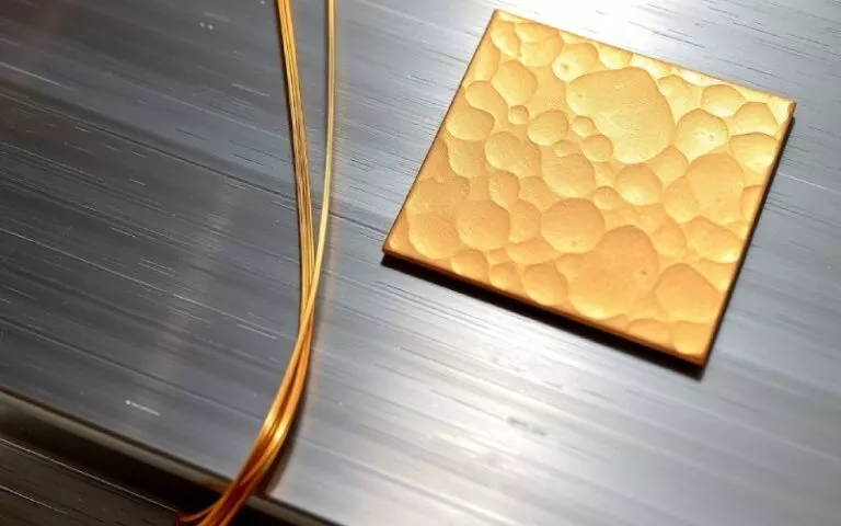
As the cutting edge engages the workpiece, the material ahead of it undergoes compression and shear. Once separated from the workpiece, the material is evacuated along the tool surface as a chip. With ductile materials, the metal undergoes significant plastic deformation prior to separation. Under appropriate cutting conditions, this typically results in a continuous chip flowing across the tool’s rake face.
Continuous chips are not necessarily a problem. In many machining operations, they indicate that the material is undergoing continuous shearing rather than fracturing into irregular fragments. The real challenge lies in controlling the chip’s length, shape, and trajectory. Consider drilling into a ductile metal: instead of breaking into short segments, the material may form long, curled chips that remain connected or wrap around the drill bit. If these chips fail to evacuate smoothly from the hole, they can interfere with subsequent cutting, scratch the machined surface, or increase the risk of tool damage.
The issue is not simply that the material is ductile; rather, it is the interplay between the material’s deformation characteristics, tool geometry, and the available space for chip evacuation that creates difficult-to-manage chip forms. Materials with lower ductility may produce shorter or more fragmented chips under certain conditions. However, low ductility does not guarantee easy chip control, nor do all ductile materials inevitably produce long, continuous chips. Factors such as cutting speed, feed rate, tool geometry, and material microstructure all influence chip formation. The ultimate goal is not to eliminate the material’s ductility, but to establish cutting conditions—tailored to the specific material and process—that produce chips which are easy to manage.
Why Ductile Materials Can Produce More Burrs
Burr formation is another significant consequence of plastic deformation. A burr is defined as the excess material remaining on the edge of a workpiece after machining. Burrs typically form when material near an edge bends or stretches instead of separating cleanly.
Consider milling a slot in a metal sheet: as the cutting tool approaches the edge of the slot, the remaining material thins and loses structural support. If the material undergoes plastic deformation rather than a clean break, a small protrusion of metal may remain at the edge; this protrusion is the burr.
Ductile materials are particularly susceptible to this phenomenon because they tend to bend and stretch before fracturing. Instead of breaking cleanly at the intended edge, the material may be pushed outward or folded over.
Burrs can cause a range of practical issues. They may interfere with assembly, compromise the fit between mating parts, alter edge dimensions, or necessitate additional deburring operations. For parts featuring small holes, narrow slots, or complex geometries, even minor burrs can have serious consequences.
Ductility is not the sole factor influencing burr formation. The orientation of the cutting edge relative to the workpiece boundary, tool sharpness, feed rate, material strength, and the support conditions beneath the cutting edge all influence the final outcome.
Engineers should address burr control during the process planning stage rather than treating it as an issue to be resolved after machining is complete. For precision parts, engineering drawings should clearly specify which edges require deburring, whether sharp edges must be maintained, and whether specific chamfers or edge radii are permissible. These specifications help determine the appropriate machining and finishing strategies for the part.
How Ductility Affects Surface Finish
The machined surface is formed as the cutting edge moves across the workpiece. Ideally, the tool removes material in a controlled manner, leaving a surface that meets specified roughness and dimensional requirements. With highly ductile materials, the process becomes complex if the material flows or smears (adheres) during cutting rather than separating cleanly. Depending on material properties and cutting conditions, the cutting edge may push material to the side, leave behind adhered material, or cause surface irregularities due to unstable chip formation.
For instance, a soft, ductile metal might appear easy to cut because the tool encounters little resistance upon entry; however, if the cutting edge lacks sharpness or the material begins to adhere to the tool, the resulting surface quality may still be unsatisfactory. This highlights a key distinction: a material that is easy to penetrate does not necessarily yield an excellent surface finish under all cutting conditions.
Surface roughness is also influenced by feed rate, tool geometry, tool wear, machine vibration, material microstructure, and finishing strategies. While ductility helps explain certain surface defects, it should not be viewed as the sole cause of poor surface quality. When ductile materials smear or leave excess material around workpiece features, adjusting tool conditions or cutting strategies is often more effective than simply lowering machining parameters. The appropriate corrective measure depends on the specific type of defect; for example, the analysis and resolution of surface issues caused by a built-up edge (BUE) differ from those caused by vibration or tool deflection.
What Is Built-Up Edge, and Why Does It Matter?
A Built-up Edge (BUE) is a phenomenon where workpiece material adheres to and accumulates on the cutting edge or the adjacent tool surface during the machining process. BUE formation occurs when factors such as pressure, friction, temperature, and the interaction between the material and the tool cause the material to stick to the tool rather than being discharged as a chip.
Ductile materials are prone to BUE formation under specific cutting conditions, as they tend to deform and adhere at the tool-workpiece interface. Aluminum and certain other non-ferrous alloys are common examples, although the tendency varies depending on the material grade, tool condition, coating, and machining parameters.
As the BUE grows, it temporarily alters the effective geometry of the cutting tool. Subsequently, the adhered material may break off and affect the newly machined surface. This can lead to inconsistent surface finish, altered cutting characteristics, and dimensional deviations.
It is important to note that BUE formation is not caused solely by material ductility; factors such as cutting speed, tool material, rake angle, lubrication, and the condition of the cutting edge also play a role. Employing appropriate tool geometry, maintaining a sharp cutting edge, and setting suitable cutting parameters can help reduce the risk of BUE formation. Specific solutions depend on the workpiece material and the type of machining operation.
Does Higher Ductility Always Make CNC Machining More Difficult?
Not necessarily. While ductility certainly presents specific machining challenges, it can also be advantageous in the right applications.
Highly ductile materials resist cracking during deformation—a valuable trait for components subjected to impact, bending, or forming operations during service. During machining, this capacity for deformation facilitates the formation of continuous chips, though it can also make chip breaking difficult and lead to stubborn burrs.
Materials with lower ductility are more prone to fracture and may produce shorter chips. However, this brittleness can introduce other challenges—such as cutting edge chipping, surface damage, or sensitivity to localized stress—depending on the specific material properties and machining operations involved.
There is no absolute rule stating that high ductility equates to poor machinability, or that low ductility equates to good machinability.
Engineers must consider how a material behaves during specific machining processes. For instance, chip evacuation might be the primary concern in drilling operations; deformation and burr formation may require greater attention when milling thin-walled structures; and material smearing (adhesion) or built-up edge (BUE) formation may be critical factors during precision surface finishing. Ductility only becomes a machining challenge when its effects conflict with the machining process or the technical requirements of the finished part.
How Ductility Affects Different CNC Machining Operations
The influence of ductility varies with the way the cutting tool engages the workpiece.
CNC-frezen
During the milling process, the cutting edge repeatedly enters and exits the material. As each tooth contacts the workpiece, it undergoes deformation and removes a portion of the material. With ductile materials, the resulting chips may be long or continuous, depending on the tool geometry and cutting conditions. Plastic deformation can lead to burr formation at the edges of slots, cavities, and external contours.
The direction of the tool path is critical, as it determines how the cutting edge engages the material and the level of support provided to the cutting edge tip. For features requiring high edge quality, the potential location of burrs must be taken into account when planning the machining sequence.
CNC-draaien
In turning, the cutting tool continuously removes material from a rotating workpiece. Ductile materials can produce long, curled chips that interfere with the cutting area if they are not controlled.
Chip shape matters because long chips can wrap around the workpiece, tool, or nearby equipment. They can also damage the surface if they rub against the component after being formed.
Chip-breaking tool geometry and appropriate cutting conditions can help produce more manageable chips. However, a chip breaker that works well for one material or feed range may not perform equally well for another.
CNC-boren
Drilling creates a particularly challenging environment for chip evacuation because the cutting takes place inside a hole.
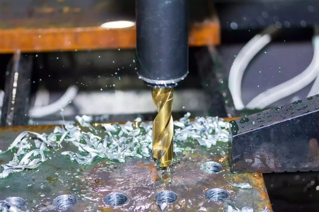
In ductile materials, long chips may remain inside the hole or become entangled around the drill. If chips cannot escape, they can obstruct further cutting, increase friction, damage the hole surface, or contribute to tool failure.
The deeper the hole relative to its diameter, the more important chip evacuation may become. Drill geometry, flute design, coolant delivery, and the drilling cycle all affect how effectively chips leave the hole.
For this reason, a ductile material that is relatively straightforward to mill may still require careful process development when drilled into a deep, narrow feature.
How Tool Selection Helps Manage Ductility
Tool selection should take into account the material’s deformation and separation characteristics during the cutting process. A sharp cutting edge facilitates cleaner shearing and minimizes unnecessary material deformation. Tool geometry also influences chip flow and the ease with which chips separate from the workpiece.
For ductile materials prone to producing long, continuous chips, using a chip-breaking feature helps break chips into shorter segments. Specific design choices depend on the material, the machining operation, the feed range, and the depth of cut.
Tool coatings and substrate materials also affect friction and material adhesion. Since the outcome depends on the workpiece material and cutting conditions, one should not blindly select a specific coating simply because the material is ductile.
The goal is to manage the interaction between the tool and the workpiece, rather than simply seeking a harder or more expensive tool. For instance, if machining aluminum alloys results in poor surface quality due to material adhesion on the cutting edge, selecting a suitable, sharp tool and re-evaluating cutting conditions is often more effective than simply attributing the issue to standard tool wear. If the primary challenge in deep-hole drilling is the formation of long chips, then chip evacuation and drill geometry should take precedence over surface finish.Adjustments to the machining strategy should be guided by the specific issues observed during the process.
How to Reduce Burrs and Control Chips When Machining Ductile Materials
The first step in establishing a reliable machining process is to clearly identify the specific problems caused by the material’s ductility.
If the issue involves long, stringy, or tangled chips, the machining team may need to re-evaluate the cutting tool’s chip-breaking geometry, feed parameters, and chip evacuation space. For deep-hole machining, coolant delivery methods and drilling cycle strategies are also critical. If burrs are the primary concern, focus should be placed on cutting edge support, tool sharpness, cutting direction, machining sequence, and the specified condition of the cutting edge. While some burrs can be minimized through process adjustments, others may still require a dedicated deburring operation. If smearing or material adhesion appears on the machined surface, attention should be directed toward built-up edge (BUE) formation, cutting edge condition, tool geometry, lubrication, and the suitability of cutting parameters.
These issues should not be conflated. Although long chips, burrs, and surface smearing are all linked to material ductility, their root causes differ and may require distinct solutions. Clarifying the expected machining outcome is equally important. The machining approach for parts that allow for a slight edge break may differ from that for parts requiring precise control of the cutting edge profile or burr-free assembly holes. Specific print requirements and inspection standards dictate the appropriate corrective measures.
Why Part Geometry Matters When Machining Ductile Materials
Ductility describes a material’s deformation characteristics, while part geometry determines where such deformation might create manufacturing challenges.
Machining easily accessible external surfaces is relatively straightforward, even when the material produces continuous chips during cutting; however, narrow slots or deep holes present significant challenges due to the limited space available for chip evacuation.
Similarly, while burrs on non-functional outer edges may have little impact on component performance, burrs inside precision holes can prevent mating parts from fitting correctly.
Thin-walled structures introduce another set of considerations. Due to limited rigidity, they are more sensitive to cutting forces and workpiece deformation. Although ductility influences how the material deforms at the cutting edge, it does not in itself determine whether a thin wall will flex or twist.
When evaluating components for custom CNC manufacturing, one must consider not only material specifications but also feature geometry, edge requirements, wall thickness, tool accessibility, and inspection standards. This allows the manufacturing team to anticipate and identify potential challenges regarding chip control and deburring before production begins.
Conclusie
Material ductility impacts CNC machining because it determines the extent of plastic deformation a material can undergo before fracturing. During the cutting process, this property influences chip formation and evacuation, burr generation, and the quality of the machined surface.
Xtmade manufactures custom parts tailored to client specifications, including drawings, material requirements, and processing needs. During the machining planning phase, we evaluate potential issues—such as chip control, burr management, and surface quality—by considering specific material properties, part geometry, and machining operations, and we formulate appropriate machining strategies accordingly. Our goal is not to avoid highly ductile materials but to fully understand their deformation behavior, ensuring a stable machining process, high-quality edges, and consistent dimensional accuracy and quality.