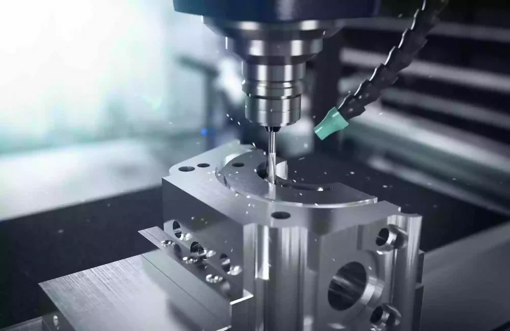
Che cos’è la lavorazione a 3+2 assi?
Quando si tratta di lavorare pezzi con più facce, le officine si trovano solitamente di fronte a due scelte estreme: continuare a utilizzare una macchina a 3 assi e sopportare il costante ribaltamento manuale dei pezzi, il loro riallineamento, lo spreco di tempo di ciclo e gli errori di tolleranza cumulativi; oppure investire in una costosa fresatrice simultanea a 5 assi e affrontare la complessa programmazione e la simulazione delle collisioni che ne derivano.
È qui che la lavorazione a 3+2 assi si rivela la soluzione ideale per ottenere un elevato ritorno sull'investimento. Il ragionamento è semplice: utilizzare gli assi rotativi per inclinare e bloccare il pezzo in un angolo specifico, per poi eseguire tagli ad alta rigidità proprio come su una macchina standard a 3 assi.
In parole povere, risolve un problema fondamentale: come ottenere una “lavorazione su più lati con un unico serraggio” utilizzando la programmazione a 3 assi più semplice e la rigidità meccanica più stabile.
Questo articolo analizzerà la lavorazione a 3+2 assi sotto 7 aspetti chiave: definizione, principio di funzionamento, configurazioni delle macchine, vantaggi del processo, ripartizione dei costi, confronto tecnico (3 assi vs. 3+2 vs. 5 assi simultanei) e linee guida DFM (Design for Manufacturing).
Che cos’è la lavorazione a 3+2 assi?
Molti si chiedono perché la chiamiamo “3+2” quando la macchina utilizza chiaramente cinque assi fisici.
Il nome, in realtà, riflette accuratamente la cinematica su cui si basa. La lavorazione a 3+2 assi (comunemente definita nel settore come “a 5 assi posizionali” o “a 5 assi indicizzati”) separa essenzialmente il posizionamento spaziale dal taglio vero e proprio in due fasi distinte:
All’inizio del processo, i due assi rotanti della macchina ruotano per orientare il pezzo o la testa del mandrino secondo l’angolo spaziale desiderato. Una volta posizionati, gli assi rotanti vengono bloccati meccanicamente o idraulicamente per garantire un fissaggio ad alta rigidità. Durante la successiva fase di taglio, questi assi rotativi non partecipano ad alcun movimento di interpolazione; la lavorazione viene eseguita interamente dagli assi lineari X, Y e Z, comportandosi esattamente come nella fresatura standard a 3 assi. Solo al termine della lavorazione dell’elemento corrente gli assi rotanti si sbloccheranno, si posizioneranno sull’angolo successivo e si bloccheranno nuovamente per il ciclo successivo.
Questa è la differenza fondamentale tra la lavorazione 3+2 e quella simultanea a 5 assi: la lavorazione simultanea richiede che tutti e 5 gli assi effettuino interpolazioni dinamiche e compensazioni durante il taglio, mentre la lavorazione 3+2 richiede che gli assi rotanti rimangano completamente statici e rigidamente bloccati durante il taglio.
Di conseguenza, a livello di controllore, la lavorazione a 3+2 assi viene comunque programmata ed eseguita come una lavorazione a 3 assi. Si tratta semplicemente di sfruttare la capacità di posizionamento spaziale di una piattaforma a 5 assi per ottimizzare le configurazioni tradizionali a 3 assi.
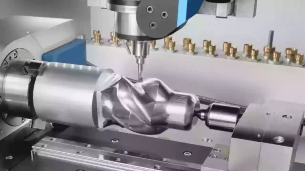
Come funziona la lavorazione a 3+2 assi
Per eseguire con successo la lavorazione a 3+2 assi, il controllore CNC, l'hardware della macchina e il software CAM devono operare in modo coordinato attraverso le tre fasi seguenti:
Fase 1: Trasformazione del sistema di coordinate (TWP)
Nella lavorazione standard a 3 assi, l'utensile si muove rigorosamente all'interno di un sistema di coordinate del pezzo (WCS) fisso. Quando gli assi rotativi inclinano il pezzo, il sistema di coordinate originale non è più perpendicolare all'asse dell'utensile.
Per risolvere questo problema, il controllore CNC utilizza una tecnologia di trasformazione delle coordinate denominata “Tilted Working Plane” (TWP), che viene solitamente eseguita tramite il comando G68.2 in FANUC o la funzione PLANE in Heidenhain.
La logica è semplice: una volta che gli assi rotanti hanno completato il posizionamento, il controller utilizza matrici matematiche per definire un piano virtuale temporaneo a 3 assi sulla superficie inclinata. Ciò consente al programma di eseguire le istruzioni standard X, Y e Z senza che il controllore debba effettuare calcoli dinamici in tempo reale del punto centro utensile, come avviene nella lavorazione simultanea a 5 assi.
Fase 2: Fissaggio meccanico degli assi rotanti
La capacità della lavorazione a 3+2 assi di gestire tagli pesanti dipende in larga misura dal suo meccanismo di serraggio fisico.
Una volta che gli assi rotanti hanno orientato il pezzo all’angolo desiderato, la macchina non fa affidamento sulla coppia di tenuta elettromagnetica dei servomotori per contrastare le forze di taglio. Al contrario, i freni idraulici o pneumatici ad alta pressione all’interno della tavola rotante o della testa girevole si attivano immediatamente. Sulle macchine ad alta rigidità, i giunti Curvic vengono spesso utilizzati per l’interblocco meccanico positivo.
Questo dispositivo di bloccaggio rigido trasforma gli assi rotanti in una struttura solida e statica, consentendo il trasferimento diretto delle vibrazioni di taglio e delle forze d’urto nella fusione del basamento della macchina, garantendo così la stabilità del processo.
Fase 3: Pianificazione del percorso CAM e transizioni
Nei software CAM, la logica di programmazione della lavorazione a 3+2 assi si basa sulla programmazione piano per piano. Il programmatore deve semplicemente definire i diversi piani di lavorazione e le corrispondenti direzioni degli assi dell'utensile. Il post-processore inserisce poi automaticamente una sequenza di transizione sicura tra questi piani. La sequenza di movimento standard è:
Ritirare l'utensile all'altezza di sicurezza → Sbloccare e posizionare gli assi rotativi → Bloccare gli assi rotativi → Affondare e tagliare.
Questa logica impedisce qualsiasi collisione tra l'utensile, il pezzo e i dispositivi di fissaggio durante i movimenti rotatori.
Macchine e attrezzature per la lavorazione a 3+2 assi
Nella produzione effettiva, la lavorazione a 3+2 assi viene eseguita su macchine CNC di marchi mondiali di prim’ordine. A seconda del progetto meccanico, queste macchine rientrano generalmente in due categorie principali:
Categoria 1: Macchine a 5 assi con supporto girevole (tavola-tavola)
In una macchina a perno, i due assi rotativi (di solito gli assi A e C) sono integrati nel piano di lavoro. Il mandrino rimane in posizione verticale fissa, mentre il pezzo si inclina e ruota come una culla. Questa è la configurazione più diffusa per la lavorazione a 3+2 assi, poiché offre una rigidità di taglio superiore.
Haas Automation — Serie UMC
Modelli rappresentativi: Haas UMC-750 o UMC-500.
Caratteristiche principali: Si tratta di macchine a 5 assi molto diffuse nelle officine di tutto il mondo. Grazie al loro prezzo accessibile e ai sistemi di controllo intuitivi, molte officine le utilizzano specificatamente come macchine a 3+2 assi ad alta efficienza per la lavorazione di collettori, corpi valvola e componenti poliedrici.
DMG MORI — Serie DMU
Modelli rappresentativi: DMG MORI DMU 50.
Caratteristiche principali: DMG MORI è un punto di riferimento nel settore in termini di precisione. Le sue macchine sono dotate di mandrini estremamente robusti e di basamenti dal design rigido, che garantiscono un’eccezionale rigidità di taglio durante l’esecuzione di cicli di sgrossatura pesanti in 3+2 posizioni.
Categoria 2: Macchine a 5 assi con testa girevole (testa-testa)
In una macchina con testa girevole, il piano di lavoro rimane fisso. I due assi rotanti (di solito gli assi B e C) sono integrati nella testa del mandrino. Il mandrino inclina l'utensile agli angoli richiesti, mentre il piano di lavoro ne sostiene il peso. Questo tipo di macchina è ideale per la lavorazione di componenti molto grandi e pesanti.
Okuma — Serie MU
Modelli rappresentativi: Okuma MU-5000V.
Caratteristiche principali: In qualità di uno dei principali costruttori giapponesi di macchine utensili, Okuma è rinomata per l’elevata stabilità termica e la rigidità del mandrino. Una volta bloccata la testa girevole in posizione per la lavorazione 3+2, la sua rigidità eguaglia facilmente quella di una fresatrice standard a 3 assi.
Mazak — Serie VARIAXIS
Modelli rappresentativi: Mazak VARIAXIS i-700.
Caratteristiche principali: Noto per le sue eccezionali capacità di multitasking. L’avanzato sistema di controllo CNC Smooth di Mazak offre un eccellente supporto algoritmico per le trasformazioni del sistema di coordinate (TWP), garantendo transizioni rapide e fluide tra piani inclinati.
Soluzione alternativa: adeguamento di una macchina a 3 assi
Se un'officina ha un budget limitato e non intende acquistare una macchina a 5 assi nuova di zecca, l'aggiornamento di un centro di lavoro verticale (VMC) a 3 assi già in dotazione rappresenta una soluzione pratica.L'approccio: installare una tavola rotante (o piatto) a 2 assi di alta qualità sul piano di lavoro di una macchina a 3 assi esistente. Marchi standard del settore: le tavole rotanti giapponesi come quelle di Tsudakoma sono ampiamente utilizzate a questo scopo, conferendo immediatamente a una fresatrice standard a 3 assi una capacità di posizionamento a 3+2 assi.
Perché scegliere la lavorazione a 3+2 assi?
Perché la lavorazione a 3+2 assi è così diffusa? Risolve proprio i punti critici della lavorazione a 3 assi e a 5 assi simultanea in tre semplici punti:
- Un'unica configurazione, nessuna tolleranza nell'impilamento: La lavorazione di più lati su una fresatrice a 3 assi richiede 5 operazioni di ribaltamento manuale, con conseguenti errori di allineamento. Il sistema 3+2 consente di lavorare cinque lati in un unico allineamento, risparmiando manodopera ed eliminando le tolleranze cumulative.
- Utensili più corti, maggiore rigidità: Inclinando il pezzo, il mandrino si avvicina alla superficie di taglio. Ciò elimina la necessità di utensili lunghi e flessibili, consentendo l’uso di utensili corti e rigidi per tagli pesanti, senza vibrazioni e con finiture superficiali migliori.
- Programmazione semplice, facile da imparare: La programmazione simultanea a 5 assi richiede complesse procedure di prevenzione delle collisioni; la programmazione 3+2 è semplicemente una normale programmazione a 3 assi su piani inclinati. Qualsiasi programmatore a 3 assi è in grado di gestirla senza quasi alcuna formazione aggiuntiva.
Analisi dei costi e analisi economica
Nello studio di fattibilità di qualsiasi progetto produttivo, il costo è un modello finanziario globale determinato dalle spese in conto capitale (CapEx) e dalle spese operative (OpEx).
In primo luogo, per quanto riguarda le spese in conto capitale (CapEx), la lavorazione a 3+2 assi offre una notevole efficienza in termini di capitale. Una macchina a 5 assi simultanei di fascia alta, importata, ha in genere un prezzo di acquisto compreso tra $500.000 e $1.000.000. Al contrario, una macchina nativa a 3+2 assi posizionali costa solo circa da $100.000 a $150.000. Inoltre, l’adeguamento di una fresatrice a 3 assi esistente con una tavola rotante a doppio asse riduce la barriera di ingresso in termini di hardware a soli $20.000 – $30.000. Ciò riduce drasticamente il periodo di ammortamento e mantiene stabile il bilancio delle officine meccaniche di piccole e medie dimensioni.
In secondo luogo, vi è un netto contrasto tra le licenze software e i costi di manodopera. La lavorazione simultanea a 5 assi richiede moduli CAM avanzati per il movimento continuo, oltre a programmatori altamente qualificati in grado di calcolare complesse distanze dinamiche di sicurezza. Inoltre, lo sviluppo di post-processori personalizzati per il movimento continuo rappresenta una spesa iniziale significativa. D’altra parte, la lavorazione 3+2 richiede solo percorsi CAM standard a 3 assi proiettati su piani inclinati. Le ore di programmazione rimangono praticamente identiche a quelle delle configurazioni standard a 3 assi, consentendo al personale di programmazione già in forza di eseguire i lavori con una formazione minima ed eliminando i rischi legati alla manodopera specializzata.
Infine, la differenza a lungo termine risiede nelle spese operative (OpEx). Le macchine a 5 assi simultanei subiscono un’usura meccanica continua e multiasse durante le interpolazioni dinamiche, il che comporta costi di manutenzione significativamente più elevati. Poiché la lavorazione 3+2 blocca meccanicamente gli assi rotanti durante le tagli pesanti, le forze di lavorazione aggressive vengono trasferite direttamente al basamento rigido in ghisa della macchina, anziché essere assorbite dai servomotori e dai riduttori attivi. Ciò prolunga notevolmente la durata dei componenti critici di azionamento e riduce al minimo le perdite catastrofiche dovute ai tempi di fermo macchina.
Applicazioni tipiche e limitazioni
Nella pianificazione dei processi produttivi, definire i limiti della lavorazione a 3+2 assi è fondamentale per ottimizzare la capacità produttiva dell’officina meccanica. Sebbene questa tecnica sia particolarmente indicata per la lavorazione di componenti complessi con caratteristiche su più lati, presenta evidenti limiti fisici quando si tratta di superfici organiche continue.
Applicazioni tipiche
Il campo di applicazione ideale per la lavorazione a 3+2 assi è costituito dai pezzi prismatici e dagli stampi con cavità profonde. Nei settori automobilistico, idraulico e aerospaziale, componenti quali blocchi motore, collettori idraulici, alloggiamenti del cambio e corpi valvola presentano numerosi fori angolati, svasature e superfici di montaggio con orientamenti diversi. La lavorazione 3+2 consente di eseguire forature, maschiature e scavi su tutte queste superfici con un unico serraggio. Inoltre, nella sgrossatura e nella semifinitura di stampi per iniezione di materie plastiche e stampi per pressofusione, l’inclinazione del pezzo consente l’uso di frese frontali indexabili più corte per la sgrossatura ad alta velocità, il che migliora notevolmente le velocità di asportazione del materiale proteggendo al contempo il mandrino dalle vibrazioni.
Limiti tecnici
Il limite fondamentale della lavorazione a 3+2 assi è l’impossibilità di eseguire un’interpolazione continua e simultanea a 5 assi. Trattandosi di un processo “posizionale”, gli assi rotanti devono rimanere bloccati e fermi durante il taglio. Di conseguenza, per i pezzi caratterizzati da curve organiche complesse — quali blisk, giranti, pale di turbina o componenti strutturali aerospaziali altamente sagomati — il movimento simultaneo del percorso utensile è indispensabile, rendendo impossibile la loro produzione con il sistema a 3+2 assi. Inoltre, se un pezzo richiede frequenti transizioni tra piani di lavorazione altamente frammentati, il ciclo ripetitivo di “ritiro, sblocco, indicizzazione, serraggio e immersione” genererà un tempo di taglio a vuoto considerevole, rendendo il processo meno efficiente rispetto alla lavorazione continua a 5 assi.
Lavorazione a 3+2 assi vs. lavorazione continua a 5 assi
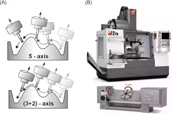
Sia la lavorazione a 3+2 assi che quella a 5 assi continui si basano su piattaforme CNC a cinque assi, ma utilizzano gli assi rotanti in modi diversi. La differenza principale consiste nel fatto che la lavorazione a 3+2 assi utilizza gli assi rotanti per il posizionamento, mentre la lavorazione a 5 assi continui impiega tutti e cinque gli assi contemporaneamente durante il taglio.
| Confronto | Lavorazione a 3+2 assi | Lavorazione continua a 5 assi |
| Movimento assiale | Gli assi rotanti posizionano il pezzo o l'utensile a un angolo fisso e si bloccano durante il taglio. Si muovono solo gli assi X, Y e Z. | Gli assi X, Y, Z e quelli rotativi si muovono simultaneamente, consentendo variazioni continue dell'orientamento dell'utensile. |
| Rigidità | Maggiore rigidità grazie al bloccaggio meccanico degli assi rotanti, che lo rende adatto a tagli pesanti e alla asportazione di materiale. | Ridotta rigidità durante il taglio, poiché gli assi rotanti rimangono in movimento dinamico. |
| Qualità della superficie | Ottimo per elementi angolari e pezzi poliedrici, ma potrebbe richiedere più configurazioni in caso di superfici curve complesse. | Ideale per superfici complesse a forma libera con transizioni più morbide e meno segni di lavorazione. |
| Complessità di programmazione | Utilizza metodi di trasformazione delle coordinate più semplici, come il TWP, che consentono una programmazione e una post-elaborazione più agevoli. | Richiede funzioni avanzate quali RTCP/TCPM per la compensazione in tempo reale degli utensili, rendendo la programmazione più complessa. |
| Le migliori applicazioni | Ideale per pezzi con più facce angolate, fori, cavità e, in generale, lavorazioni su più lati. | Ideale per stampi, giranti, pale di turbina e componenti curvi complessi. |
Nella produzione pratica, molti produttori combinano entrambi i metodi: la lavorazione a 3+2 assi viene utilizzata per la sgrossatura e la semifinitura al fine di massimizzare la rigidità e l'efficienza, mentre la lavorazione continua Lavorazione a 5 assi viene utilizzato per la finitura finale di superfici complesse.
Linee guida DFM per la lavorazione a 3+2 assi
Per massimizzare l'efficienza e ridurre i costi, applica queste 4 regole rapide di DFM durante la progettazione:
- Ridurre al minimo i piani di indicizzazione: Raggruppare gli elementi angolari (fori, asole) su un numero di piani il più ridotto possibile. Una rotazione minore comporta tempi di ciclo più rapidi.
- Assicurarsi che vi sia spazio sufficiente tra i dispositivi di fissaggio: Lasciare un margine di serraggio di 3–5 mm nella parte inferiore del pezzo in caso di morse sopraelevate. Ciò impedisce che il mandrino entri in collisione con il dispositivo di fissaggio durante l'inclinazione.
- Ottimizza i raggi degli angoli: Aumentare il raggio degli angoli interni da 10% a 20% rispetto al raggio dell'utensile da taglio per evitare vibrazioni nelle cavità profonde.
- Allineamento dei fori obliqui: Allineare gli assi dei fori obliqui in modo che siano paralleli, ove possibile. Ciò consente alla macchina di forarli in un unico ciclo, evitando ulteriori indicizzazioni.
Conclusione
La lavorazione a 3+2 assi rappresenta il perfetto compromesso tra semplicità e prestazioni. Utilizzando la programmazione standard a 3 assi per ottenere una produzione “un unico allestimento, più lati”, garantisce la massima rigidità e un ottimo ritorno sull’investimento per collettori, alloggiamenti e componenti di stampi complessi.
Noi di Xtmade sfruttiamo una tecnologia CNC multiasse all’avanguardia per dare vita a questi progetti complessi. Il nostro esperto team di ingegneri DFM esamina i vostri file in fase preliminare per eliminare eventuali interferenze, ottimizzare i piani di lavorazione e ridurre le operazioni di configurazione. Che abbiate bisogno di prototipi rapidi o di componenti destinati alla produzione, Xtmade rende la produzione ad alta precisione semplice, veloce e altamente conveniente.